A Spreadsheet for Inductor Design on EI Cores
May 2026, Ver 0
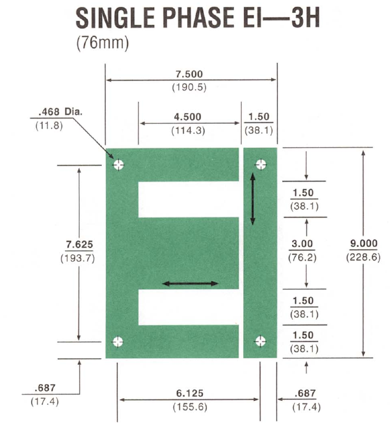
The core shown above is the biggest EI cores I've used in a design.
The design had to have a frequency response flat to 0.4 dB down to less than 2 Hz.
The spreadsheet shared here uses the same design techniques used to design the 2 Hz Beast, but the spreadsheet didn't exist yet when the beast was designed.

Presented here is a spreadsheet method to design inductors on an EI core. In this method, you get to pick the variables listed below. After you pick these values, you decide if you can both "afford" the part and if you can physically "lift" the part. If you are clever, you can even use spreadsheet to design the primary winding of a transformer. The variables you get to specify are:
1. The inductance of the reference winding at the peak current
2. The peak current of the reference winding where the inductor hits the design flux (Gauss) level)
3. The DC resistance of the reference winding
4. The Gauss drive (Tesla / 10,000) and
5.
The window fill factor (one of the manufacturing parameters.)
Note: In this spreadsheet 100% full is 100% full (not counting the bobbin): don't use 75% fill like with some other design methods.
Once you pick these items, the inductor parameters are fully bounded and can be uniquely designed using the Inches^5 design equation:
(LI)^2/{DCR} = K_c * (U_r H)^2 * (A_c^2 * A_w)/{MTL} * 1/{pd^2} * {A_p}/{A_w}
Paul's IEEE presentation for using the Inches to the Fifth equations (PDF)
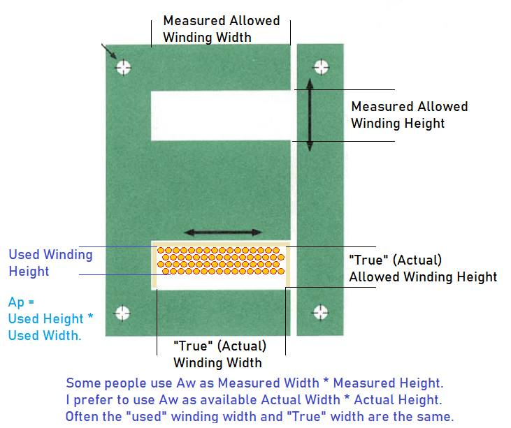
Once we understand how to design a linear inductor with DC bias, we can then properly design a transformer with or without DC bias. The biggest design difference between designing an inductor and a transformer is that with an inductor we can use 100% of the "true" (not measured) available window area for the copper's (Aw/Ap) window fill factor and with a transformer we use 40-60% of the "true" available window area for (Aw/Ap). Why not use exactly a 50% fill factor for a transformer? That is because we occasionally want to optimize power losses, balance the losses in multiple windings, add extra insulation to the high-voltage side to reduce capacitance or make design changes to improve manufacturability and/or improve the robustness of the design. The "game" isn't optimizing just 1 parameter; it is achieving the best balance between all the parameters.
The "Inches to the Fifth" design method works nicely because on a Linear Inductor, E = L di/dt which becomes E dt = L di. This linearization allows us to use that the voltage integrated over time (E*T as in Volt*Seconds) = Inductance * Current. The ET is calculated over half a cycle at a given frequency. This is because over a full cycle at a given frequency, the average voltage is ZERO (ET=0). If it wasn't zero, the DC bias point would be changing.
Example:
If we have a 20 Henry inductor at 50 mA DC bias for 0.40 Volt*seconds of DC "ET" with a sine wave voltage across it that occupies 0.36 Volt*seconds (a zero to 45mA swing in inductor current), the inductor has to support 0.40 + 0.36 = 0.76 Volt*seconds peak as it swings from a bias current of 5 mA to 95 mA (50 mA + 45 mA) in steady state.
For a transient (tone
burst), the peak current in an inductor in the plate of the output
tube can be different than the peak current in steady state. Not
because the "Inches the Fifth" equations are defective, but because
of how the circuit operates and a desire to keep from overloading
the transformer or a desire to have the inductor not go "dry" (hit
zero current.) For more on this topic, see the notes from the old
discussion located here: 2X
flux
margin needed for a tone burst. ) An example is shown
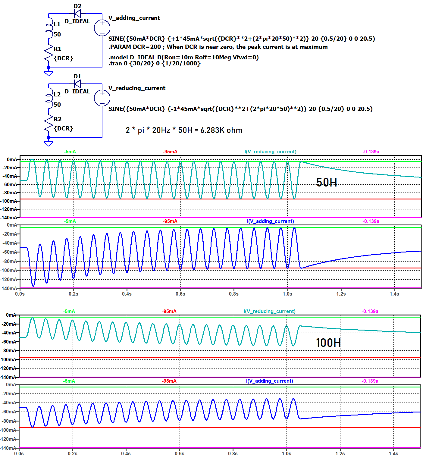
below, showing the need for very high inductances to reproduce a low
frequency tone burst. If you don't want the inductor to saturate
during the approximately 135 mA (135 mA -95 mA = 40 mA) overshoot
during a tone burst with a 50 H core, set the DC design current 40
mA higher when sizing the core and then go back and remove the 40 mA
when looking at temperature rises. If using the spreadsheet, you can
also just drop the frequency for maximum output power in half (i.e.,
drop 30 Hz to 15 Hz.) Personally, I'd just raise the inductance
instead.
To see how with 100H the current in the inductor with the tone burst behaves better in the plots below [ The Blue I(V_adding_current) trace ].
Off topic:
Could this transient effect be one of the things contributing to the "Polarity" effect seen in Audio Electronics where changing the polarity of the signal to an amplifier or speaker changes the sound coming from that speaker?
The derivations of the inductor design equations and related articles are located here:
IEEE PDF Presentation on DCR based Inductor Design
Derivation
of the Single Iteration DCR based Inductor Design Equations (For
the Uber-Nerds only.)
Lowell Quist's
Audio Transformer Design Example
Lowell
Quist
on Regulation Based Transformer Design.
HELP! It looks like there is a lot of maths involved and someone new to the equations could easily fat-finger the data entry. Please make my brain hurt less!
Yes there are a lot of Maths involved.
To make the design of inductors with DC bias easier, I've loaded the design equations into an Excel spreadsheet. A friend in the Audio Industry has used this spreadsheet and gave me some feedback on it. They liked it, but they said it didn't fill the bobbin full. Because they gave me useful feedback (and feedback other than "I misspelled something again") I had no issue with letting them have a copy of it to use in their business. However, if you make a lot of money with the design program, please feed me a few pizzas and a couple six packs of Dr. Pepper (Cane Sugar Dublin Dr. Pepper if you can find it) as payment.
When using the spreadsheet, remember that the window fill factor normally in this spreadsheet runs conservative. 100% really is a full window, not 70% like when using older design methods. Even with that, I normally shoot for 90% as full so I have room for a bobbin and so I can tweak the design for cost and performance later in the design process. In other versions of this spreadsheet, I've made core tables of the AW*AC/MTL with my favorite bobbin window area used on the core.
Download Excel File for the Inches to the Fifth, EI Inductor Design Spreadsheet
SAFE Voltage: 50V peak or less ( Google: UL Safe Voltage ). If the part works above the "Safe Voltage" at any point of operation, the magnetic will need something other than magnet wire insulation between the circuit and the users of the part.
Failures from corona are a different
issue that takes dozens of pages to cover. If a red-light-running
truck doesn't end me, I'll talk about that some time in the future. If
the no signal voltage to peak AC voltage at 20 kHz is less than 200
Vpk (in 3 dimensions), corona control is easy; just address the DC
voltage stresses. If it is above 300V to 400V peak, you really need to
start to "think" about controlling the AC voltage stresses. Above 400
Vpk, you need to start "doing" something about it. An easy control
method is to add a layer of tape every 200 Vpk of winding and limit
all sharp points in and next to the high voltage winding. Vacuum
varnishing the part doesn't fix many corona issues. Corona control is
about eliminating both sharp points and entrapped air. A vacuum pour
with a pressure cure (> 80 psi) in a potting cup with a thin epoxy
works miracles for eliminating corona but introduces other issues.
The units used on the page for the derivation of equations are:
L Inductance in Henries
lm Magnetic path
length in centimeters
la
Effective air gap in centimeters
Ac Actual iron
cross sectional area in square centimeters
Aa Effective
cross sectional area of the air gap
Aw is the available
winding area of the core in square inches
Ap is the area
occupied by the wire in the primary of a transformer or the wire of
an inductor in square inches
d is
the insulated wire diameter in inches
p is the
Ohms/1000 feet, milliOhms/foot, or Ohms/12000 inches of the wire
H oersteds
I Amps
Uo 0.4*PI*1E-8
for lm in cm and Ac in square cm
Ur Relative
permeability (dimensionless)
N Turns
I
Current in Amps
F Fringing
factor
Kstk Ratio of the actual iron
area to physical iron area
Gauss Tesla/10,000
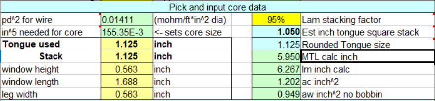
I normally use inches when designing with EI cores.
Give a rough estimate of the iron weight.
Give a rough estimate of the copper winding turns and wire gauge for the inductor version or for the primary winding if using this to design a transformer.
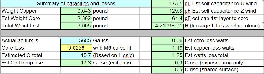
Give a rough estimate of the self-capacitance and leakage inductance of the inductor/transformer primary. If using this as an actual transformer, the leakage inductance will be a bit more than twice the estimate in the spreadsheet.
Give a rough estimate of the temperature rise of the surface of the part (not the hot spot internally, the just surface temperature rise.)
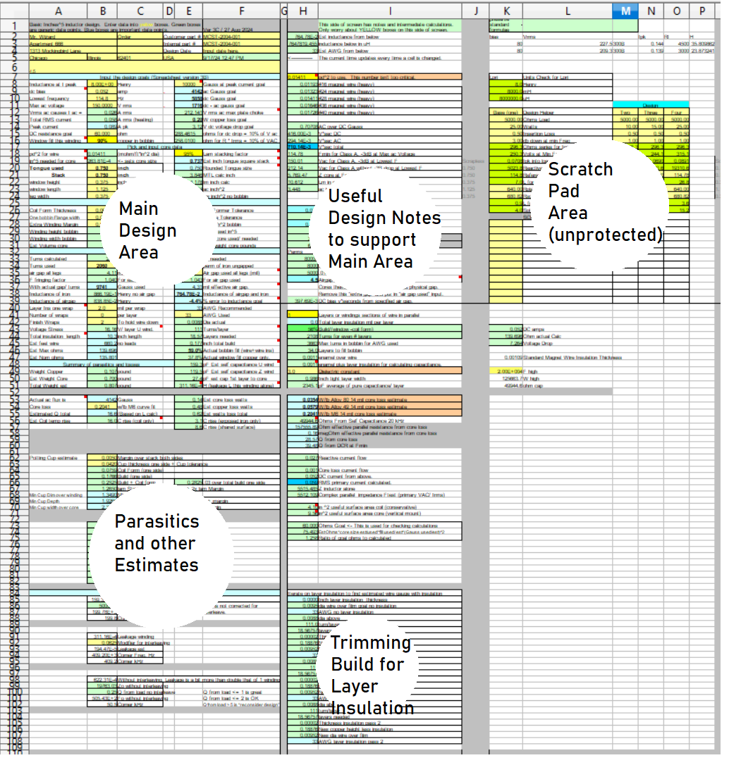
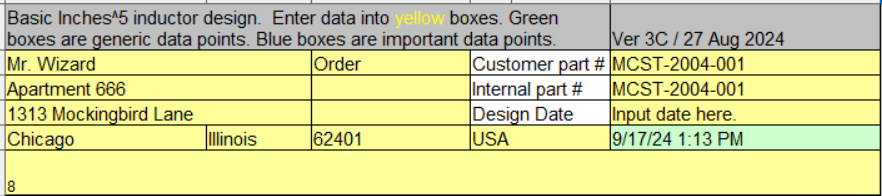
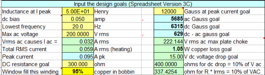
The spreadsheet is broken up into several areas. Inputs are in the "yellow" boxes and should all be "unlocked."
The % window fill can be tricky when correcting for the bobbin and winding insulation. If the final DCR is higher than the goal, this % was likely set higher than what the final design ended up with for the copper fill.
Don't automatically use low peak gauss numbers. If you want to add margin to the design, raise the DC bias current, drop the lowest frequency, or use a higher AC output voltage.
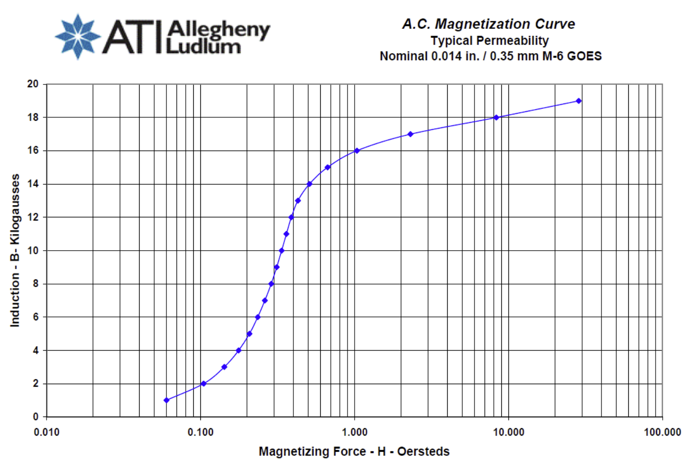
It is the slope of the BH loop that
we care about. 15k Gauss (kG) for M6 material is a decent design
point. At just over 15 kG, the slope of the BH loop (permeability) is
close to the slope we will get at just over 1 kG. A low nickel core
will have a steeper (better) slope at low gauss than what we get with
M6, but low nickel will saturate at a lower peak kG.
I don't know how hard it is to get
large laminations in 49 percent nickel in larger laminations in the
year 2026, but if you keep the Gauss down to 9.5 kG, you'll get a
significantly higher core permeability and you'll get lower core loss.
The HP49 plot below is from a DU shaped test core, it will better
match an EI core's performance than a strip wound core's curve.
When I use Alloy 49, I normally use it in a C-Core. When I need
a small-sized inductor and don't care about cost, I use Supermendur
(Cobalt), but with Supermendur, you
give up high permeability at low Gauss.

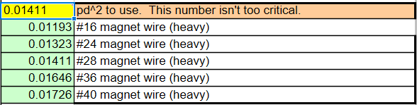
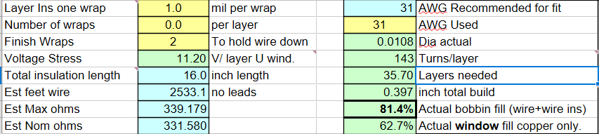
Don't overthink this parameter. For a small change in AWG, there is only a small change in pd^2. Pick the number for #28 AWG for 30-100 mA and pick the #16 AWG number for winding currents in amps. Avoid designing with #36 AWG and finer wires; they are easy to damage during manufacturing. The same goes for single-build magnet wires, avoid them for they damage easily. Use the heavy-build magnet wire.
The suggested tongue size is based on
a calculated square stack of scrap-less EI laminations and is rounded
to the nearest 0.125 inch. The recommended core size may not
exist, but this gets you in the ballpark. A 1X, 1.5X and 2X stacks are
common. A higher than 2X stack is not common.
I normally see 95% used for the Lam
stacking factor. If you are really careful aligning the burrs on
the iron, you can do slightly better. Don't scratch the
laminations up too much, the Phillips Milk of Magnesia they often
insulate the cores with isn't very thick.
A "funny story": A customer once put one of my mentors through a living "hell" proving that the "mint-flavored" version of the coating works the same as unflavored.
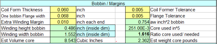
You can use a paper coil form or a molded bobbin. COSMO bobbins is one of the suppliers for bobbins for EI cores. Google searches for winding bobbins don't get many good hits in 2024.
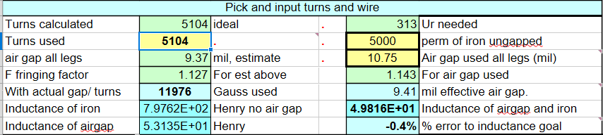
5000 perm for the iron is a common number to use when designing on M6. Low nickel cores (HP49) will have a higher ungapped perm than M6 iron. Avoid 80% high nickel cores in anything that is stamped or cut; 80% nickel is very sensitive to mechanical shock and strain.
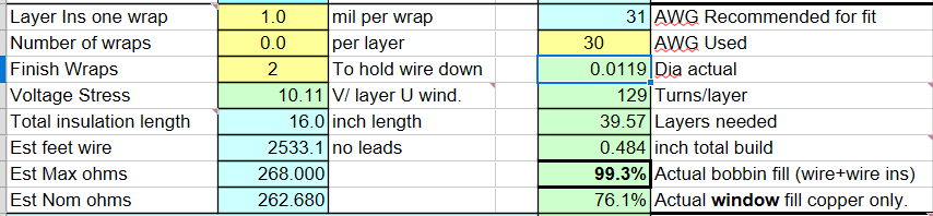
You will want to play with the number
of turns in the winding to get full layers in the bobbin. I often
leave 1 turn off the last winding layer to account for the lead-exit
bend. On a transformer, 1 turn out of 1000 is hard to measure. 1 turn
out of 100 is significant. On an inductor, 1 turn out of 100 isn't a
big deal as long as the inductance is correct.
The airgap will be set by the flatness of your stack of laminations, the available thicknesses of Nomex paper you have in stock, and the available thickness of fiberglass sheets you have in stock. The core itself can have 0.5 to 3 mils of gap with no paper.
The calculations automatically correct for a small amount of fringing and for having the gap both in the tongue and in the outer legs. A large amount of fringing is considered to occur when the air-gap is the same thickness as the coil former/bobbin thickness (including any air under it.) When the fringing gets to be large, the coil "pushes back" on the fringing field and the equations are no longer correct (plus you pick up extra AC power loss.)
The spreadsheet only covers "layer wind" window fills. If you go for a "Hexagonal" fill, you can sometimes can get 10% more copper build. Usually "hexagonal fill" doesn't achieve this 10% more because of manufacturing limitations.
While I didn't "cook the books" on this example, it worked better than normal. Normally I don't get this close. We wanted 300 ohms DCR and got 331 ohms. We wanted 12kG and got 11.9kG and we wanted 50H and we got 49.8H.
The surface temperature rise is based
on a formula from a power supply application guide I had from the
1970-80s. I can't find this guide back to give it credit. The copper
losses are from the DC bias current and the current from driving the
core at maximum voltage and minimum frequency. These currents do not
include the load current if it is used in a transformer application.
If we change to 30 AWG we go up to 99.3% fill and get 263 ohms DCR. It may actually fit. If it doesn't, we have to pay for the wire we wasted and have to buy another prototype. Your budget will decide the risk.
I
haven't used this program in more than a decade. I'm a bit concerned
that I didn't pull the latest version from the dozens of versions I
have. If you find something that doesn't pass a sniff test, let me know
via Audio Asylum mail. I decided to release this spreadsheet "as is"
because the next time a "BLEEPING" truck runs a red light, I may not
brake fast enough, and my planned web pages and ideas I want to share
may never get released. I did teach that truck how to count to 132 in
binary.
The RMS current calculated in the spreadsheet is the "unloaded" primary RMS current when excited. It does not include the current from the load.
How
big does a 5K ohm, 0.25 dB insertion loss, 80 H, 60 mA dc, 11W input
(output from the tube) SET have to be?
The primary DCR is approximately: 0.5 * 5K ohm * [
10^(0.25dB/20) - 1 ] = 73 ohms primary DCR.
This
design iteration ends up with a very small (likely unrepeatable) air gap
of 2.75 mils.
I would be tempted to increase the insertion loss (primary DCR to 150 ohms) to increase the number of turns. This will make the gap larger.
I
would also be tempted to increase the primary fill factor to 55% and
leave 35% for the secondary. The "pile" of insulation would be the
remaining 10%.
If
I had the money, I'd also make this from low nickel laminations (about
49% Ni) and thus have to drop the gauss down to 9500.

This
is a big guy. 12.2 pounds. I think I'd switch things up to get
down to a 1.5 inch tongue.
I
do not recommend single-film insulated magnet wire insulation. One of my
transformer design mentors pulled out an industry spec and showed me
that magnet wire insulation is allowed to have a certain number of
defects per 1000ft. If you use double-film magnet wire, the probability
of these defects lining up is near zero. Some Mil magnet wire
specifications don't allow voids (defects) in the wire insulation; I
think they may be missing a fact of life.
I
avoid 105 C wire because of the high cracking and crazing risk, even
though the wire is easy to heat strip. There is a heat-strippable 200 C
Thermaleze out there that is more robust and that is also fairly easy to
heat strip.
The
air gap thickness is corrected for being in both the center leg and the
outer legs. The air gap is not corrected for the surface roughness of
the iron in the gap. A C-core will use an air gap closer to what is
calculated than EI laminations. Make sure the gap is correct with DC
bias applied before varnishing the core. I've seen the inductance be
different with zero bias when compared to a few percent of the DC bias;
this is also from the surface roughness of the iron. Make the inductance
correct with DC bias applied, not at zero bias.
On
high-performance designs, after setting the gap, I'll ask that the part
be varnished with the screws loosened about 1/4 turn and then the screws
retightened. I sometimes ask that if I provide the DC bias fixture, the
varnish be dried with DC bias applied to the part. This drying method
adds cost, but it can reduce acoustic noise.
Inductors
can have "polarity." The capacitance from the start winding to the air
and both the case and the parts next to the inductor will be different
than the capacitance from the end winding to the air and both the case and
the parts next to the inductor. Some times this difference in
capacitance matters; many times it doesn't.
In
transformers, parasitic capacitance (polarity) can matter more because
the capacitance from primary to secondary can regularly impact circuit
performance.
The
Hitachi Wire Guide is really good. A lot of good stuff is in the
footnotes. READ ALL THE FOOTNOTES! Hitachi Magnet Wire Guide
I'm
curious to see how well an ETFE-insulated wire part would work vs.
adding layer insulation on each layer. We would be trading a lower labor
cost for a higher material cost to use the EFFE. I'd lean towards using
ETFE over PFA because ETFE has a higher cut-through resistance when
compared to PFA and FEP, but it is stiffer than both. One issue with
using ETFE over enameled magnet wire would be that with ETFE, the fill
factor would be 2.7 times lower because of the higher pd^2 wire factor.
The winding tension will have to be monitored, for even ETFE can have
cut-through issues (the insulation cold flows over time and makes a
short).
For
some
time now I've been using LibreOffice
instead of MS Office. I've purchased MS Office many times, and I'm
tired of updates that I don't like or need. The only thing in MS
Excel that I miss is the ability to format numbers in "Engineering
Notation" (the exponent is in multiples of 3 decades, 10E3 instead
of 1.0E4.) Google Sheets doesn't work well for me. It takes
too much effort to make a local copy on my hard drive vs cloud-based
storage.
LibreOffice's Calc does have the "Goal Seek" function that I lean on heavily. It works the same as "Goal Seek" in Excel. "Goal Seek" is powerful. I had an eager young engineer start to do detailed partial derivatives on a group of complex equations so we could optimize a design. I hinted there was an easier way, but he was "eager" to use his expensive engineering degree. I already had the math in Excel opento check the results during our discussion. To prove my point, I ran "Goal Seek" on the result's cell and we got the answer in minutes instead of days. . . Rock beats scissors. Scissors beats paper. Paper beats rock. Mouse annihilates paper . . .
First version 2-Sept-2025, Last update 05-May-2026.
15-may-2026 added more comments and fixed some grammer..
Yes in Aug I made a change to correct a couple font issues, that
doesn't count as an update.
 (
New 2024 index page.)
(
New 2024 index page.)
 _( Old 2003 index page.)
 _( AMP Second index
page.)
( Fancy index page.)
_( AMP Second index
page.)
( Fancy index page.)