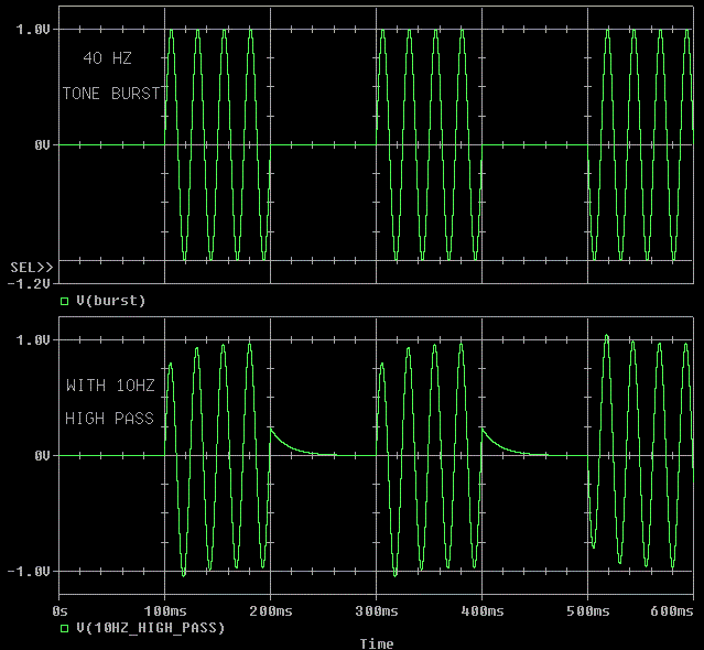
The top waveform is a perfect DC to light tone burst.
The bottom waveform is what happens when we add a simple 10 Hz -3 dB cut
off.
If you have suggestions on how to improve this web page,
contact me (VoltSecond) through private e-mail off the TUBE DIY Asylum.
For a transformer output amplifier, low frequency steady state sine waves are easier to make than a burst of sine waves that start and stop.
The top waveform is a perfect DC to light tone burst.
The bottom waveform is what happens when we add a simple 10 Hz -3 dB cut
off.
We care about tone bursts because most music is closer to tone bursts than to steady state sine waves. This is why it is important that we can make reasonably clean tone bursts. If your 40 Hz tone burst looks like the lower one in the picture above, crack open a Dr. Pepper and don't bother to try to improve it any further. I wish to point out that even if we can make perfect tone bursts, that does not guarantee good sound; however, if we make lousy tone bursts we can pretty much count on mediocre sound. Tone bursts are just one ingredient in the mix.
An easy rule of thumb for tone bursts through transformers is that you have to support full power at 1/2 the frequency of the tone burst to have a chance of making an undistorted (clean) tone burst. This means if we want a clean full power tone burst at 40 Hz, we need to support the same voltage steady state sine wave at 20 Hz. For this presentation I want to first consider an ideal parafeed (or push-pull type) transformer driven from a low impedance source. Next, I'll add a few parasitics. Finally, I'll discuss a SET plate transformer.
The primary inductance of a transformer is the same as any other inductor, it obeys E = L * di/dt + I * dL/dt. If the inductor is linear, the I * dL/dt term is zero. Because we want and design our inductors to be fairly linear, we normally only consider the E = L * di/dt part.
Technical Note
First edition 1-06-04, Last update 1-06-04
The voltage integrated over time determines the flux in a transformer. "Voltage integrated over time" is a fancy way of saying "average voltage between two points." When the flux reaches the saturation level of the transformer, the transformer will reach a certain amount of current and then go non-linear. The current that flows at saturation is unique for each inductor and transformer design. The current that flows at saturation should be consistent for a give manufacture's model. For example: George's Garage Model 13A should saturate at 13 mA for all 13A serial numbers, but Model 15C may saturate at 300 mA for all 15C serial numbers.
Remember the voltage over time across the transformer causes a current to flow, not the other way around. I will be using a linear transformer in this discussion so that we can watch the current closely to find out where the saturation occurs. Also, to keep the models simple I will only use the primary inductance of the transformer, not the entire transformer.
Steady state is what happens when the signal has been present for a very long time. Practically, steady state is a signal that has been present for at least 5 times the longest system time constant. The system time constant is not the period of an applied sinewave, but how long it takes the amplifier (the system) to settle after a transient.
Steady State
First edition 1-06-04, Last update 1-06-04
Because the current into the primary is the sum of the magnetization current (what we are watching for saturation) and the load current, I am not adding any load resistance at this point in the discussion.
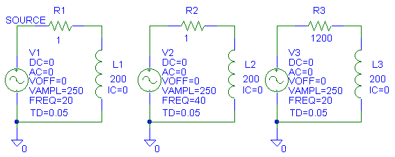
To view steady state, this is the circuit we'll use:

L1 and L3 see the same signal, except that L3 sees it through a 1200 ohm
resistance
(800 ohms r_plate + 400 ohms DCR (winding resistance.))
L1 and L2 see the same impedance, but at two different frequencies.
Because I am using an ideal LINEAR inductor, we will assume that
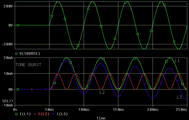
saturation on this particular 200 H inductor occurs at 10 mA. We can see
below that L1 is running just at saturation at 250 V pk, 20 Hz in this
example:

L2 [red], which is running at 40 Hz, is running 1/2 at the saturation point. The 1200 ohms in L3's source isn't making much of a difference between L1's and L3's current flow because 200H at 20 Hz, ( 2 * pi * 200H = j25,132 ohms) is still much larger than 1200 ohms.
Also note that the current is at maximum when the voltage goes through zero. This is consistent with the flux being at its peaks just before the voltage goes through zero. L1 and L3's current goes from -10 mA at the first zero crossing of the voltage to +10 mA at the next zero crossing of the voltage. This is a peak to peak swing of 20 mA. During the next half voltage cycle, the current goes from +10 mA back to -10 mA for an average change in current of ZERO.
Notice that L2 only swings half the current because it is at twice the frequency. Not only does L2 swing half the current, it swings half the Gauss because the "average voltage * time" over one half sine wave is half due to the period of the sine wave being half as long.
In THIS LINEAR inductor consider +10 mA to be 16,000 Gauss (positive peak
saturation) and -10 mA to be -16,000 Gauss (negative peak saturation.) So
L1 and L3 are swinging 32,000 Gauss peak to peak, (a 16,000 Gauss sine
wave design point.) L2 is swinging 16,000 Gauss peak to peak (which would
be an 8000 Gauss sine wave design point for a transformer that carries
zero DC current.)
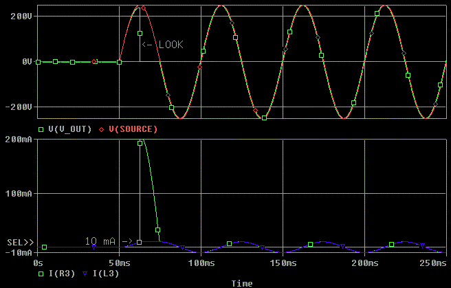
Now, let's just put a tone burst into an inductor. Remember, the inductor
simulates the primary inductance of the transformer and if the current in
THIS inductor exceeds 10 mA, the inductor has saturated.
First notice that the voltage leads (occurs before) the current. Next notice 20 Hz inductor currents (L1 and L3) both saturate and the 40 Hz current almost saturates!
Why did the 20 Hz tone burst current go past the saturation current?
Remember that L1 swings 20 mA (32,000 Gauss) peak to peak in one half of the 20 Hz sine wave. Since at idle, the current is zero, when the tone burst (sine wave) starts, it tries to swing from 0 to 20 mA (0 to 32,000 Gauss) . When it hits 10 mA, it will saturate causing the inductance to drop to near zero. Because at 40 Hz, the inductor L2 only swings half the current peak to peak (half the flux peak to peak), it CAN support the tone burst.
The first half cycle of the tone burst is like a DC offset. It causes a DC current flow in the inductor. L3 shows this effect as the peak to peak current moves closer to being centered around 0 mA as time passes. The DC current flow is causing a voltage across R3 to occur and is allowing the average current and the average Gauss to reach zero over time.
At this point I could end the web page and say:
"See. To support a 40 Hz full power tone burst you need to support full power at 20 Hz."
However:
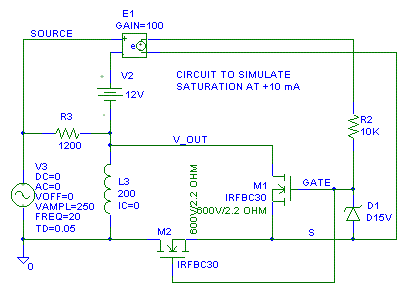
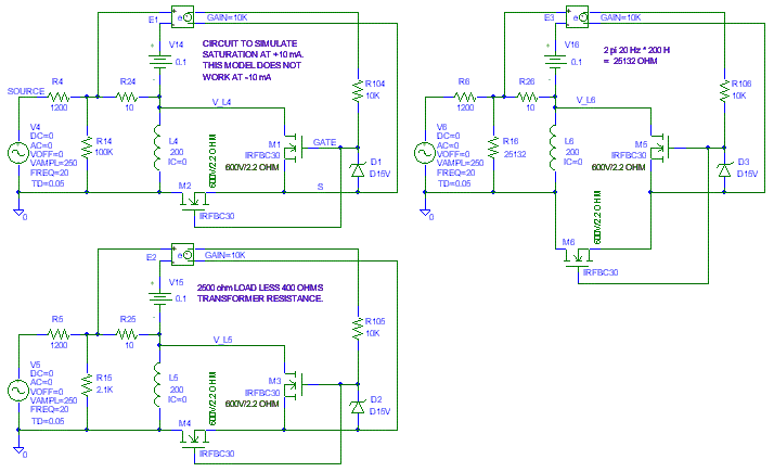
Since I don't have a good Pspice model of a real saturating 200H inductor
at 10 mA, I am going to invent one. When the current through R3 reaches 10
mA, we'll short the inductor out with M1 and M2. We'll monitor R3 to see
the effective current through L3. This models an inductor that saturates
hard (i.e. has a rapid drop in inductance). Inductors that saturate
softer. Saturating softer means we won't have as abrupt of change in
inductance. This model only works for "positive saturation", but that will
be enough for what we are about to look at.
Notice the scale change on the current measurement. It is now 200 mA full scale, not 20 mA.
When the inductor saturates, look what happens. The inductor adsorbs every mA of current the source can supply through the impedance (R3) that is feeding the inductor. The voltage across the inductor drops to zero while the inductor is saturated (meaning the music will go away briefly.) However, at the end of the first half cycle, the inductor is back to normal.
I also plotted the current in L3 to show that the saturation simulator is
actually causing saturation when 10 mA is flowing in L3. The actual
current seen by the voltage source when saturation occurs is the current
in R3, not the current in L3.
Why did the inductor recover after the first half cycle of voltage?
When the current in L3/ R3 reaches 10 mA, the inductance of L3 drops to the point where all the applied voltage is dropped across R3 and L3 does not see any more voltage during the half cycle. This limits the flux in L3 to its positive saturation level from about Time = 62.5 ms to Time = 75 msec in the plot above. As soon as the voltage changes polarity (crosses zero) the flux in L3 drops and the L3 comes out of peak positive saturation. Now signal can appear across L3 meaning the music has returned. When the inductor came out of saturation at the zero crossing of the tone burst, it was at the same current (flux) level as steady state. Hard saturation put us back to normal operating conditions faster with non-ideal components than with ideal components.
Real world inductors often take several cycles to stop saturating. This is mostly because they don't saturate as hard as shown in the model. The first half cycle will saturate approximately as shown in the example above, but the next couple positive half cycles will have smaller duration of saturation. Remember, while the transformer is saturated, not much music is made.
The source impedance of 1200 ohms consists of 800 ohms from r_plate (r
sub p) of a tube and 400 ohms primary resistance from the transformer. The
load impedances I picked are 2500 ohms (a common load for a 2A3), 25K ohms
which is a load that matches the X_L of the inductor at 20 Hz and 100K, an
arbitrary large load. Because the transformer has 400 ohms primary
resistance, I'm going to only use 2.1K (2500 ohm - 400 ohm) for the load
impedance. I will also use a hard saturating model again for these plots.
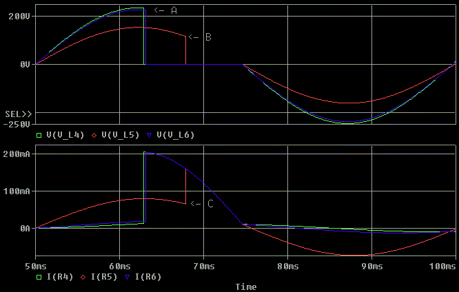
With a tone burst into this model we get the following response. Note
that this time we are looking at the current delivered by the source, not
just the current in the inductor.

Saturation is where the voltage across the inductor is rapidly dropping to
zero or where the current draw is spiking.
Notice that at point "A" the output voltage is a little lower than normal because of the saturation of the transformer. The plots for the 100K and 25K loads are almost on top of each other. Also notice that matching the load impedance to X_L of the transformer did not cause much of a change in the saturation point of the output signal because X_L is large (has lots of ohms) in this example. With a transformer that has a softer saturation, this drop won't be as abrupt.
Point "B" (2500 ohm load) saturates later in the sine wave because the voltage across the inductor is less. The voltage is lower because the 2100 ohm load impedance drops the output voltage by 36% as compared to the lightly loaded voltages. Loading the source voltage will change the saturation point because there will be less voltage across the inductor.
Point "C" (2500 ohm load) saturates after the load current has
peaked. Where the inductor saturates will be set by the average voltage
across the inductance of the transformer, not the current flow through
primary. Also note that the 2500 ohm loaded model is drawing a lot
more current from the source than the lightly loaded models. Below is a
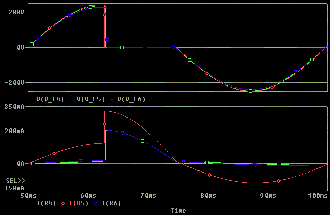
close up of the first cycle of the tone burst.
As shown below, if we increase the source voltage so that the same
voltage appears across the inductor with the 2500 ohm load as the 100K
load, they will saturate at the same point. In this next plot I increased
the voltage "V5" by (2100 +1200)/2100 = 1.57:1 or to 392V peak. The source
voltage must now deliver more current because it must drive voltage across
both the load and the inductor. Notice that the inductor now saturates at
the same point (the same voltage) as the unloaded inductor model. Any
differences in the saturation points are because of rounding errors in
setting up the simulation. Remember, the voltage integrated over time
across the inductor is what is causes the inductor to saturate.
Now I'm leaving V5 at 392V peak, but I'm increasing all the frequencies
to 40 Hz to show that the 2:1 margin rule holds true in the loaded
condition.
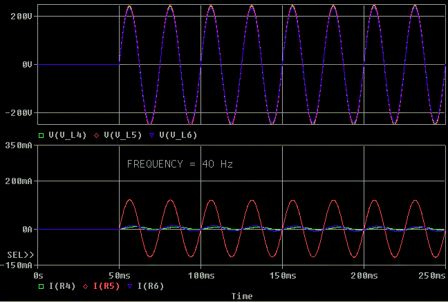
As seem below, if we drop the frequency 10% to 36 Hz with V5 still at
392V peak, we see that we are back to saturating. The saturation occurs
for a smaller portion of the tone burst, but it is still occurring.
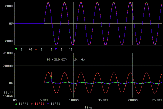
From the close up below at 36 Hz we can see that when we are close to
saturation like we are now, slight differences in voltage make noticeable
changes in how far we get through the sine wave before saturation occurs.
This is because as we are approaching the zero volts crossing, we are
accumulating voltage * time (volt*seconds) very slowly. Even at 39 Hz we
can still see some saturation, I am showing the problems at 36 Hz so the
problems are easier to see.

One final twist in this discussion:
How much do we have to turn the power down to support a tone burst at 20 Hz?6 dB is enough to capture my attention. Here is a 20 Hz tone burst at 1/2 voltage (V5 = 196V and V4, V6 = 125V).The answer is 5.2 dB or about (1.8:1 in voltage) with the set up we have above.With a zero ohm voltage source, it would be 6.0 dB (2:1 in voltage).

Moral of the story, Part 1
With a transformer whose X_L does not load the signal source, you have to support a full voltage sine wave at 20 Hz to be able to support a full voltage tone burst at 40 Hz. Why support a 40 Hz tone burst? We need to support a 40 Hz, possibly even a 32 Hz, tone burst to be able to reproduce music made with acoustic instruments. Do we sell our amp/ iron and buy a new amp/ iron if we can't make a 16 Hz tone burst? No. We can raise the - 3 dB point a little, use and active crossover to a sub or just turn the volume down a little.
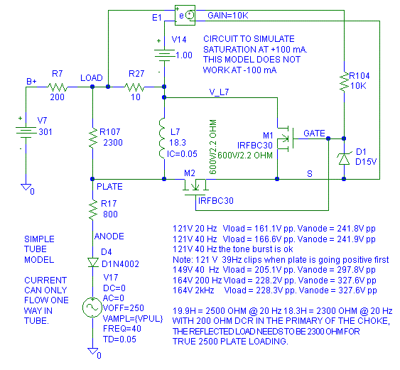
First, how do we define full power at 20 Hz in a SET when the frequency response is also 3 dB down at 20 Hz because of the inductive reactance? I will define it as the maximum undistorted loaded voltage at 20 Hz. Why? Once I find out the maximum output power at 20 Hz, I intend to hold the voltage of the frequency generator/ tone burst generator constant and just adjust the frequency of the generator. I don't intend to use the power ratings the marketing department would want to used.
Here is the circuit model I'm using. I am using a diode (D4) to simulate
the tube's ability to only sink current, it cannot source current from
it's plate. Note that V_load undistorted is 3 dB down from 2 kHz at 20 Hz
[ 20 * log (161.1V / 228.3V) = -3.0 dB ]:
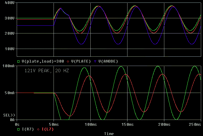
This is the tone burst at 20 Hz, notice how it clips on the first half
cycle. It is clipping because the tube can only sink current, the tube
cannot supply current to assist the inductor in pulling the voltage
upward. The inductor doesn't even run out of current.
Now, I'll keep the grid voltage the same and double the frequency to 40
Hz. Notice that it tries to clip, but just quite doesn't go non-linear. So
if we define, full power at 20 Hz as I have, the 2:1 frequency rule holds
between full power at the lower frequency and a full power tone burst at
twice the frequency.
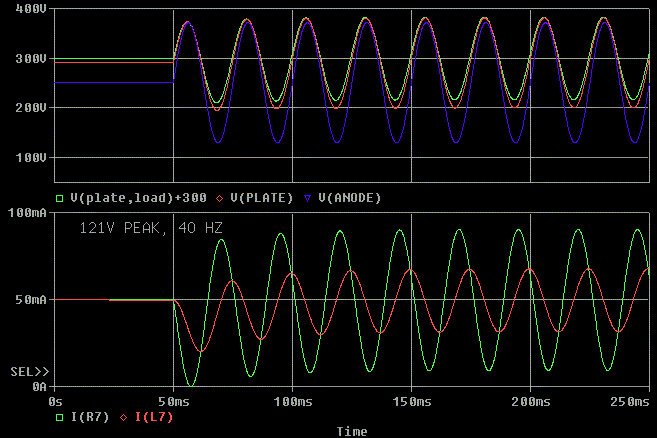
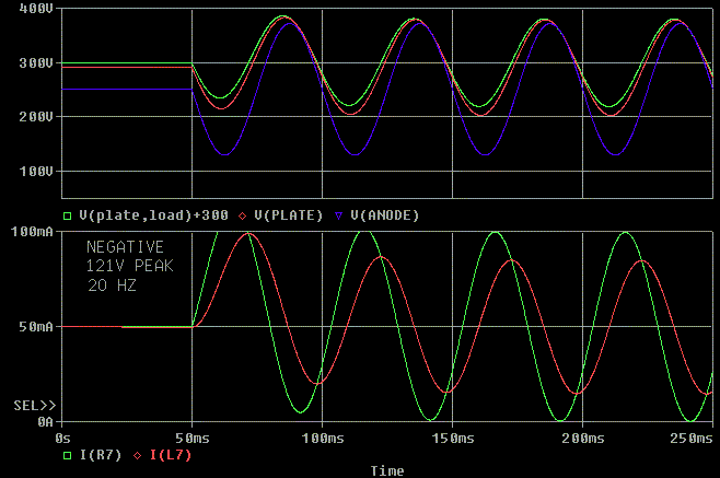
What happens if the voltage is the opposite polarity at 20 Hz? If you look below, we actually can theoretically make the 20 Hz tone burst in the opposite polarity if the tube can sink extra current. This means the tube could (if biased right) sink the extra current needed (112 mA peak) to generate the 20 Hz tone burst. There is only a little compression on the first half cycle as the inductor gets charged up. However, this successful tone burst really doesn't matter. We never really know which polarity the music will take so we can't guarantee the tone burst operation 20 Hz 121V, but we can guarantee it at 40 Hz 121V.
Now for something to really make our brains hurt.
Moral of the story, part 2
With a distortion free SET, just as with a transformer, you have to support a full voltage sine wave at 20 Hz to be able to support a full voltage tone burst at 40 Hz if you don't have control of the "polarity" of the tone burst.
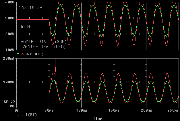
We all should know that a single tube without feedback does not create a
perfect sinewave. It compresses the waveform near the peaks at full load.
So what happens if we use a better model for our tube than a pure
sinewave, fixed resistor and a diode?
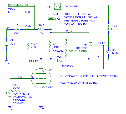
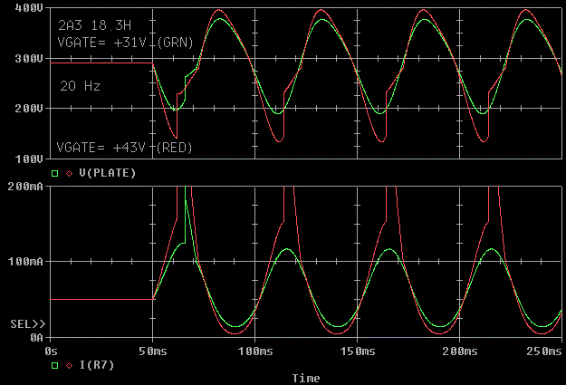
In the simple sine model, the plate going positive first had the most
problems. This corresponds to the grid going negative. I determined that
at 20 Hz, 31V was the maximum I could put on the grid of the tube at 20
Hz. I plotted both 31V and 43V on the grid. Notice that the 31V curve has
a very distorted first half cycle on the plate both at -31V and -43V, but
at 31V, the distortion mostly goes away on the second sine cycle. The
nonlinearity of the tube actually helped out on the 20 Hz tone burst.

OK, let's flip the polarity of the tone burst on the grid. This was the
easier test with the linear tube mode. I plotted 31V and 43V so we could
get a feel of what was happening. We clearly see that at 20H, the "full
power" tone burst causes magnetic saturation on the first half sinewave.
Notice that even after the first cycle of sinewave that the sinewave is
not pure. This is different than the pure sinewave results (look at the
plate voltages to keep the polarity the same.) This time the tube
nonlinearity hurts us.
Let's increase the "positive grid" tone burst up to 40 Hz. The tone burst
even at 43V almost works. Because of the tube nonlinearity, this doesn't
match our clean sinewave model of the tube. 40 Hz is still much cleaner
than 20 Hz.
Let's check the "negative grid" tone burst at 40 Hz. The first half cycle
is still compressing, but not too badly.

Moral of the story, part 3
With a real world SET that has distortion, the rules are not completely clear. You probably still have to support a full voltage sine wave at 20 Hz to be able to support a full voltage tone burst at 40 Hz.
1. Most inductors and almost all transformers have a non-linear inductance. This makes predicting the saturation current at a given frequency and voltage harder to predict. I used 10 mA for a 200 H inductor. Depending on the materials used and the size of the part, the saturation current could be from microamps to kiloamps.
2. Holding the core material constant and winding method constant, anything you do to raise the saturation voltage at 20 Hz will cause something else to worsen. Adding turns increases insertion loss (DCR), worsens the damping factor (DCR), always increases the leakage inductance and usually increases the winding capacitance.
. .
 ( New
2024 index page.)
( New
2024 index page.)
 _( Old 2003 index page.)
 _( AMP Second index
page.)
_( AMP Second index
page.)
 ( Fancy index page.)