SOME OF THESE MODS WILL BREAK
THE CURRENT PRODUCTION VERSION PARAMOUR.
CHECK YOUR SCHEMATIC AGAINST THE MOD BEFORE YOU TRY
IT.
I don't know when the production changes occurred
I know how to tell the versions apart.
I do not have a copy of the manual or schematic for
the current version Paramour.
I do not know if the terminal numbers are the same
in your version and in my version amp.
Please do NOT send me questions directly. Post them on the
Bottlehead
forum.
I am only a hobbyist collecting notes from the forum and adding my own
two cents worth.
From what I have seen so far, if you have a problem/question, a dozen
others have it too and have not spoke up yet.
If I missed an archive of interest that should have a link on this web
page or have an error on this page,
go ahead and e-mail that info to me directly or post the info on the
forum.
You'll occasionally find my email address on the
Bottlehead
forum.
I've gotten zero advertiser SPAM from being registered on the forum.
However, I don't risk listing my email in the text of posts.
Note: 1. When you register, you can block Forum emails if you want to
too.
2. When you register, you have the option of deleting your own posts.
Most of these Paramour notes are based on the first (non-C4S) version
of the Paramour.
If the notes are for the C4S version, I will say so. Most of these notes
work for both versions.
On this web page, new links will be at the top of the collection of
links.
New things I try will be at the end of this page just before the napkin
sketches.
Updated to individual sections will have the dates changed.
In Netscape 4.7, You can use {Edit} {Find in Page} to
search for text.
In Internet Explorer, you can use {Edit} {Find (on This
Page)}
Keep in mind that all tubes amps (and preamps), not just the Paramour,
have dangerous voltages and materials in them.
Play safe! Play at your own risk. I'm not kidding!
Note: Many of these first group of links to pictures don't work anymore or are intermittent (one day they work, the next they don't. They may be available on the Way Back Machine ).
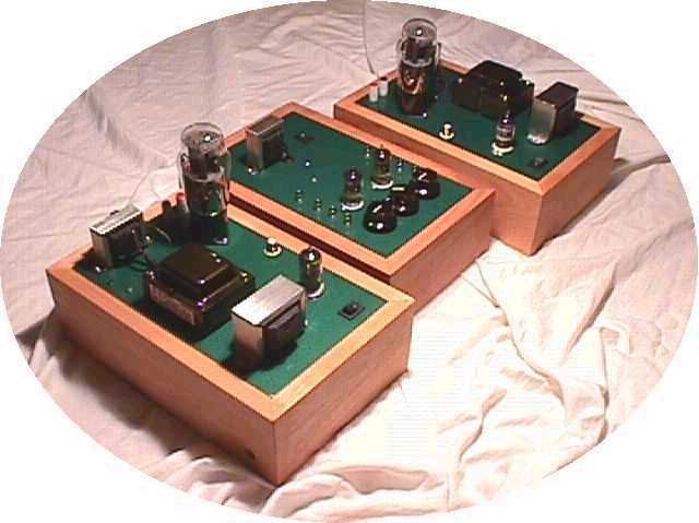
Funk Wrench's
Paramours (22 May 02)
Patrick's
Paramours
(3/9/02)
Doc's
custom
built Paramour with copper tape on 12AT7 (OK 9/20/01).
Voltsecond's Paramour
before upgrading the iron (OK 9/20/01)
Jeffrey J's Paramour (OK 9/20/01)
Kurt
Vogel's
Mirror Imaged Paramours (OK 9/20/01)
Numa's
Paramours (OK 9/20/01)
Sam's
Paramours
(OK 9/20/01)
Berlin's
Paramours (OK 9/20/01)
RBP's
Paramour
with double output iron (Link problems 8 Jun 01).
Manny
E's
Paramour with polished transformers (lost link 9/20/01)
If you'll post a link to a picture of your Paramour, I'll add it to the links above. To post a picture, the picture must reside on the web, not on your hard drive. Once it is on the web, put the complete URL (web address) in the "IMAGE" line on a forum posting. Once I see it, I'll add a link to it. Put "Paramour pictures" in the title of the posting. This will help me out for I have been short on "hobby" time since Christmas 2000 and no longer can read every posting.
If the link you publish gets deleted, the picture won't link and no one will be able to see your Paramour.
These links will only work for as long as the site they take you to is active. Use the browser's back arrow to get back to this page. If you are interested, I recommend clicking on other responses to the following posts for more information.
How to tell new power transformer from old power transformer. (4-Sep-04)
The original paramour (non-beta) offer for sale.
Paul Joppa's circuit description of Paramour from Bottlehead ForumParamour's upgrade path links
RBP's review of the Paramour
Secrets of Home Theater and High Fidelity review of Paramour
VoltSecond's Idea for a Grid Resistor Trick (17 Aug 2002)
Well Garland tried it. . .It worked. (25 Aug 2002)
Instructions on doubling up the Paramour output iron (27 Jun 2001)Paramour Reviews
More on doubling up the iron (28 Jun 01)
Dueling calculators (Parallel or Series Primaries for double output iron) (26-Mar-02)
Garland's comments on double iron (27-Apr-02).How to install the BCP-15 choke in the Paramour (28 Jun 01)
Patrick's Tube Rolling Notes for the Paramour (9-Jun-01)
470 uF for cathode bypass from Paul Joppa (13 Aug 01)
0.1 uF Hovland for coupling cap -Paul Joppa (14 Aug 01)
Using a 76 in the Paramour as a driver (19-Sep-01)
76 driver in Paramour with battery cathode bias. (16-Oct-01)
John EH likes the 1.5 uF parafeed caps and more.
C4S Questions (starting 21 Sep 01)
Paul Joppa on bias point of 12AT7 variations (21-Sep-01)Older upgrade links:
VoltSecond's notes on adjusting B6 voltage with the C4S installed (22-Sep-01).
Paramour hum and tube rolling
Untried Paramour cathode resistor mod
Some upgrade things for volunteers to play with.
Putting 45's in the Paramour More on 45's in the Paramour
Big Studs in Paramour
Notes on Paramour hum, noise and diodes.
Mod to reduce the hum and noise.
Post that says it worked well.
Preview of what Doc will put in Bottlehead's first factory Paramour mod kit
Shielding filament wires reduces hum (12/07/00).
2A3 grid coupling capacitor value change experiment
Update on coupling capacitor.
Untested opinions on using ferrite beads and magnet wire in a SET.
More Capacitance on B+, mixed results.
Try polypropylene or PIO on B+ instead of aluminum
The B+ capacitor can be as big as you can afford to buy and make fit.
Paul Joppa's upgrade ideas for the iron in the Paramour
Doc's method to C4S the Paramour
First report: C4S'd Paramour sounds good.
Some crackling on clipping, looking for an answer
Changing the B+ from CRC to CLC filtering helps with hum and improves clarity.
Changing taps on output transformer for better bass (tap dancing)
Cardas binding posts fit Paramour chassis perfectly (Thanks Patrick)
Paul Joppa's hints on C4Sing the Paramour.
Mirror Imaged Paramours (Kurt Vogel)
Which is the best 2A3 for the Paramour? (Check the links after this post.)
Paramour & Speaker compatibility (See responses to this post.)
Paramour can use just about every 2A3 out there with no modifications.
Tube Rolling in Paramour
Can you modify the Paramour for more power out with Sovtek 2A3s? (Yes, start over from scratch and re-use the tube sockets.)
Short Bolts #1 (11 Nov 2000) Bolts too sort #2: Just call Doc. (23 Apr 01)
Don't worry about black marks inside the Sino 2A3s from the mica spacers.
Sovtek 2A3's in Paramour. (Read all links below this one too!)
The Bottlehead C4S can be used with an existing the VoltSecond Hum and Noise Mod.What are the differences between the original Paramour and C4S Paramour?
Results from C4Sing a Paramour (1 May 01)
Double up your Paramour output transformers for better everything (10 May 01).
Notes on installing noise part of hum and noise reduction into C4S's Paramour (26 May 01)
More 12AT7 tube rolling from Patrick (9 Jun 01)
Check the ground ohms to find wiring problems (9 Jun 01)
Paramour part value issues:
Possible change from 499 to 680 ohms in the cathodesParamour Debug notes (also see rest of this web page for help):
A 510 ohm is sometimes shipped for the 499 ohm value and the 510 ohm is not a problem.
Doc's troubleshooting guide.
Just a nasty hum/ buzz even when fed no signal (First time reported)Paramour miscellaneous:
Fix for short screws on early power transformers. (I have notes on this below too.)
Part 2 of above link.
Scratch on outside of laminations is not a problem.
Terminals 12, 14, 17, 25, A1, A3 and A4 read high ohms
Solution: Terminal 14 wired wrong
Terminal 25 should read 200 not 2 ohms.
Take resistance readings to signal ground (tab on the RCA), not safety ground (chassis).
Lots of Hum
Solution: Fix grounding on RCA (see correction to page 39/40 )
Blue Glow from 2A3s in Paramour
Quest says that blue glow is normal in the next post.
Paul Joppa's debug notes for 377V on B1 and 36V on B8
How much power is twice as loud.
Driving other than 8 ohm speakers with the Paramour.
Tube life. (Bottlehead treats their tubes nicely, so expect to get what the tube will give.)
Patience, the Paramour 240V version is in the works.
Bottlehead sells an autoformer to take 240 V down to 120 V AC.
One of the early recommendations for the Paramour.
What is a beta Paramour? (Don't click here if you know what Beta means.)
How hard is the Paramour to build? #1
* 510 ohms is just as good as 499 ohms in the kit. A 510 ohm is sometimes shipped for the 499 ohm value and the 510 ohm is not a problem.
* Suggestion to put masking tape over power transformer winding during build to keep lead clippings out of transformer. (From Maldar Clippings where they don't belong. )
* Parts list error on Page 13, there should be 4 (not 2) 270 k ohm 1/4W resistors. (Voltsecond)
* Page 24, after all the magnetics are mounted but before you start soldering check these points for an open (infinite resistance):
OPEN Terminal 8 to Terminal 23If you measure a short, you have a problem with the installation of your bushings. (VoltSecond. There is more on transformer installation below.)
OPEN Terminal 8 to Tab on output transformer next to terminal 1
OPEN Terminal 8 to Tab on power transformer next to terminal 6
* Not a manual error, but on Page 32, bottom: I found it was easier to mount the 270 ohm 5W resistor from terminal 5 lower hole (Page 32 bottom) to terminal 15 lower hole (Page 34 top) before I mounted the capacitor between terminals 4 and 5 (page 32 middle). I soldered the resistor on both ends before the capacitor was mounted. When soldering, be careful not to get solder in the upper holes.
* On photographs of layout and page 35 (reported by Wes (Error in pictures) )
"Correction to Paramour Kit Photographs In and With the Manual
We have discovered a circuit wiring error appearing in the photographs.
One of the wires leading from the plate loading choke (C7X) is connected to terminal 14 in the photographs.
It should instead be connected to terminal 15 – as the manual text states."
* Page 39 (reported by Marting (Page 39 issue) )
"The very last item at the bottom of page 39 should read "Solder the resistor lead to" (it continues on the next page) "the cupped end of the RCA jack's center post." The reference to the 3' piece of 20 ga. magnet wire should be ignored. Instead you should (on page 40) "Cut a three inch piece of yellow off cut wire and strip both ends." and go on from there."
A second opinion from Voltsecond:
On page 40, my 499 ohm resistor did not have long enough leads to
route from the RCA ground to terminal B8. I hooked the resistor to
terminal B8, dressed the resistor out radially from the tube, parallel to
the chassis plate. I then took the 3" piece of magnet wire and use it to
hook the resistor to the ground tab on the RCA ground jack.
* This is not really a manual error, but on Page 42, make sure you route the power cord through the hole in the base before you solder the power cord to terminals 8 through 10. If you are planning to eXperiment buy an variety pack of nylon cable ties, after the power cord is routed: use a large nylon cable tie and put it on the power cord just the inside the chassis. Locate it so that if you tug on the power cord's plug, the power cord inside the unit does not pull or wiggle the wires going to the solder joints on terminals 8 through 10. Depending on the size of the cable tie you buy, you may need more than one cable tie. The instructions in the manual for tying down the power cord are for a more permanent installation. (Voltsecond)
* Page 42 After soldering the power cord to plugs 8, 9 and 10, clip all excess lead off to prevent the 115V power from hitting the chassis. There should be less than 1/8 inch of uninsulated wire exposed on both sides of terminals 8, 9 and 10. (Reported by Patrick (Fix for Blinding Flash from long 115V leads) )
* Page 43: Terminal 25 should read 200 ohms not 2 ohms to ground. (Reported by Marting ( Terminal 25 ) )
". . . I talked to Doc on the phone yesterday. The manual should read 200 ohms not 2 ohms. Your reading of 194 should be fine. I had 196 on mine."
* Add to last page: Put all the left over insulated wire and magnet wire from the Paramour construction in a baggie for storage (just in case you add mods later.)
* From posting on the Bottlehead forum, the screws were short on early power transformers.
If the nut is taller than the amount of screw extending past the bushing, you have a transformer with short screws. STOP assembling the Paramour. CAREFULLY remove the nuts from the transformer but leave the lock washer on the transformer. (Some transformers did not have a lock washer under the nut either.) Put the transformer nuts in a baggie just in case you need them later. Throw the used nuts away later after the amp is working.
* The alignment of the screws as they go through the holes in the chassis is critical, make sure the screws do not touch chassis.
I recommend checking for greater than 10K between each screw and chassis both before and after you put the last twist on the nuts to tighten them down. Screw to screw normally reads short, but can also read open. After you add the wiring, it may be too late to check for shorts to chassis on the mounting screws. Check the output transformer for shorts to chassis too. The plate choke is normally grounded, so it will measure a short to chassis.
You may have to scratch the surface of the screw, nut and/or chassis to get through any paint, varnish or oxide build up to get an ohm meter reading. Touch both probes to the same screw/nut to check for contact before you measure to the chassis metal. After you read an open, touch both probes to chassis to make sure you could actually read a short.
The screws can even short to chassis with the bushing installed. A way to prevent this is to put the bushing into the chassis plate first and then figure out how to get the screws through the holes in the chassis mount. I used a heavy duty X-Acto knife to cut the holes a little bigger and a little oblong. I prefer the large metal shavings from the knife to the fine dust from a file. If you need to open the screw holes more than a few sheets of paper in thickness, remove the nuts and loosen the screws.* Removing the nuts is done by:* Wear safety glasses in case the blade breaks.
* Cut the metal gently from both top and bottom sides of the chassis plate to keep the hole straight (not conical)
* Don't scrape the hole bigger, shave it bigger. Scraping will make the blade break and make a rough hole.
* Cut so that if you slip or the blade breaks, you don't get hurt.
* Check for burrs and metal shaving being trapped in holes.
* Clean up the mess before you continue so you don't scratch up the finish and so that you don't get metal shavings in the circuitry.*** Another way to do this is to remove the nuts and slightly loosen the screws. That way you don't have to shave the holes larger.
* Carefully scraping the varnish out of the slots of the screw heads. Soften the varnish with by touching it a Q-Tip soaked in acetone (paint grade) if necessary. Acetone is very very flammable. Keep the acetone in a chemical dispenser. A spark 6 feet away from you can ignite the acetone! I recommend using the acetone outside the house far away from flame or spark sources..
* Soften the varnish on the exposed threads with acetone per above.
* Place the transformer on a soft rag or carpet remnant, use a nut driver on the nut and a screw driver on the screw head. Turn the nut driver to remove the nuts, don't turn the screw driver blade.
* DO NOT drop the transformer!
* If one screw comes loose during the removing of nuts, smile, this is a good thing. I only needed one loose screw (on the transformer) to get the transformer to fit.
* If there is a lock washer under the transformer's nut, leave it there. It will help space the transformer over the chassis a bit more for better cooling of the parts under the chassis.
With the bushings and lock washers, some nuts will be hard to start on the screw threads. Don't force it. That is a good way to cross thread the screw. To fix this, take the lock washer off, gently start and then tighten the nut (but not all the way tight - no grunting allowed when tightening!). After the nut is tight, take the nut off. This will compress the bushings and any paint build up on the chassis and transformers. Now you can put the lock washer on the screw thread and properly tighten the nut.
As you tighten the nuts, make sure the bushing is properly seated in the mounting holes and is not just getting crushed.
If you have 10 coats of paint (like I do) plus the original coat of varnish on the magnetics, I recommend that you go to Radio Shack or Home Depot and buy at least six (two sets of three washers per amplifier) more star lock washers. Put one of these lock washers between each screw head and transformer (or inductor) mounting tab that has a ground lug on the nut side. These will bite through the paint and varnish on the magnetics and allow you to get a good ground to the magnetic's frame. I also recommend this trick for even those of you who only have the original varnish on magnetics. (Hint! Hint! Include these 6 washers in the kit!)
Note: I have two coats of color and two clear coats on all of my screw heads too.
If the lock nut (star washer) is placed between the nut and the terminal strip, the terminal strips will like to turn as you turn the nut. If you place the lock nut between the terminal strip and chassis instead, once the lock nut bites into the terminal strip, the terminal strip will no longer turn.
Because the lock nut will keep the screw threads under tension, there will still be some locking action on the nut.
I started the terminal strip about 15 degrees from where I wanted it and it ended up in just right the right position with the nuts just one little grunt tight. (15 degrees = the distance between 12 and 1 between the hands of an analog clock.) Do not tighten the speaker posts or RCA jack "one grunt tight," one of my "grunts" has stripped both plastic and RCA threads more than once. ;-)
Do not try to restrain the terminal strips as you turn the nut. I did and damaged one. (I fixed it with epoxy gel.)
When you check ohms, do not probe the solder joint. Probe the unsoldered terminal.
If you want to be extra cautious, check that every lead of every part on
each terminal reads about the same resistance (with in 1%) except for
those terminals marked with a (1). Terminals marked with a (1) will
usually read differently every time you read them.
| Terminal | Ohms | Terminal | Ohms | Terminal | Ohms | ||
| 1 | 222 | 9 | Open | 17 | 272K | ||
| 2 | 209 | 10 | Open | 18 | Open | ||
| 3 | Open | 11 | 1185 | 19 | Open | ||
| 4 | 0 | 12 | 0 | 20 | Open | ||
| 5 | 330K (1) | 13 | Open | 21 | 294k | ||
| 6 | Open | 14 | 0 | 22 | Open | ||
| 7 | Open | 15 | 2 meg (1) | 23 | Open | ||
| 8 | Open | 16 | Open | 24 | Open | ||
| 25 | 197 ohms | ||||||
| A1 | 1197 | |
B1 | 470K (1) | |
||
| A2 | 3.4 meg (1) | |
B2 | Open | |
B6 | Open |
| A3 | 272K | |
B3 | Open | |
B7 | 272K |
| A4 | 1197 | |
B4 | Open | |
B8 | 496 |
| |
B5 | Open | |
B9 | Open |
| Terminal Red | Terminal Black | Ohms | |
| B9 | B4 | 0.7 | |
| B5 | B4 | 0.0 |
| Terminal | Ohms | Notes | DVM Diode check Red to T5 |
Reading | DVM Diode check BLK to T5 |
Reading | ||
| 15 | 268 | 1 | 275K (1) | 1 | 0.45 | |||
| B1 | 269 | Reading should be the same as 15, my 1 ohm difference is from meter accuracy/precision. | 2 | 3 meg (1) | 2 | 0.47 | ||
| A2 | 534 | |||||||
| 21 | 536 | Should be the same as A2, 2 ohms off is from meter resolution |
| Terminal | Spec | My reading | Notes |
| 1 | 315 AC | 327 | |
| 2 | 315 AC | 328 | |
| 5 | 395 DC | 407 | |
| 15 | 380 DC | 391 | |
| A1 | 60 DC | 63.6 | |
| A2 | 365 DC | 377 | |
| A4 | 60 DC | 63.7 | |
| B1 | 380 DC | 391 | |
| B2 | 185 DC | 179.6 | |
| B3 | 188 DC | 182.4 | |
| B6 | 185 DC | 179.9 | |
| B8 | 2.0 DC | 2.57 | More than 10% out. I may have a bad 12AT7. |
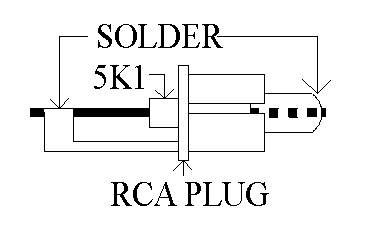
You can use 2K up to 10K in this plug when it is used for audio. Don't waste a gold RCA on this! Use the cheapest RCAs Radio Shack has to make this.
An extra idea: It was reported a long time ago that if you made plugs like the one above with 75 ohm resistors and plugged these 75 ohm plugs into un-used video and CD player digital outs, your system would sound better. Back when I tried it, my system was not as good as it is now and I did not hear a difference. Now my system is better and I need to make a few 75 ohm terminators to try it out. 75 ohms on an audio input won't hurt anything, but it could mask a hum problem because it is too low in ohms. 75 ohms on an audio output could overheat a signal source.
Buy the C1 aluminum capacitor based on:
1. Life expectancy at 105CBuy C2 based on:
2. ESR at 10 kHz
3. Size mechanical
4. Size electrical (bigger uF is better.)Go ahead an bypass C1 with a film if you want. I actually recommend it. For C2 I used a 22 uF 500V from Tubesandmore.com.
1. Mechanical sizeNote: I tried several things that did not work before I came across this first mod. Now that the Paramour is quieter, I need to retry some of those things just in case the original noise was masking any potential improvements. Of all the mods on this web page, I recommend this mod the most.
2. Cost
3. Electrical size (bigger uF is better technically, I doubt you'll hear it.)Any cap good for pulse applications should work here: X7R ceramic, Z5U ceramic, Film and foil, non-inductive metalized Polyester. DO NOT WASTE MONEY and put paper in oil here! I'm planning on trying an aluminum here once I can find the right junk box of aluminum capacitors. I doubt I'll hear a change, but I've been wrong before. For C2 I used a 0.1 uF 1000V ceramic I bought at Fry's electronics.
Link to Patrick's write up of how to install the Hum and noise reduction mod Ver 1.
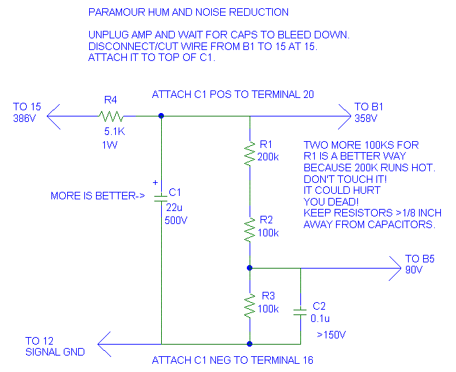
What is the Hum and Noise Reduction Mod Doing?
Added 03/30/01:
There is a significant amount of capacitance from the 12AT7's filament winding to the HV winding in the line transformer. This capacitance causes a large voltage to appear between the cathode and filament. If this voltage is too large, marginal tubes will start to conduct current from the filament to the cathode.
To see this, go ahead and carefully measure the 12AT7's pin 9 to ground voltage with an AC voltmeter. Please note that the AC voltmeter will load this voltage down because this capacitor coupling effect is high impedance. By loading the voltage down I mean that when you remove the AC voltmeter, the actual voltage will be higher than what you read with the voltmeter.
The voltage the winding to winding capacitance couples to the filament also couples a significant amount of buzz (not really hum, but buzz) from the filament to the cathode. This buzz makes it way into the speakers through the gain of the 12AT7. The filament caps take care of this problem. "The Fancy Hum and Noise Reduction Driver Mod Ver 2A" below attenuates the noise better than the basic version above.
Note: The rating for the filament to cathode voltage in a 12AT7 is 90V. Since the upper tube runs around 170V DC on the cathode and 2V on the bottom tube's cathode, a 90V bias gives 88V to the lower cathode and 82V to the upper cathode of the SRPP.
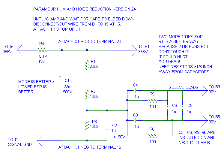
The Fancy Hum and Noise Reduction Driver Mod Ver 2A
Added 12/09/00:
IF YOUR POWER TRANSFORMER HAS
TABS INSTEAD OF LEADS
THIS MOD WILL BREAK YOUR VERSION PARAMOUR.
For your information (FYI): Version 2A was added to my Paramour that also had a non-inductive polypropylene 10 uF cap across the 2A3's filament, version 1 hum and noise reduction mod, the 0.1 uF HV diode snubbers and the lossy parafeed cap installed.
Technically version 2A is a more robust way of filtering the filament, but being better technically does not mean it has to sound better or different.
Notes:
(17-Jul-01) Do not use film for C3, C4, C5 and C6. These capacitors need to be ceramic to restrict the noise that radiates off of them.
I've had three comments about this mod killing the noise but it was also killing the music.
Two of the three had used film capacitors for C4, C4, C5 and C6. (I suspect the capacitors were inductively wound.)
One had used ceramics, but had installed a CMC filter
Yes I played safe and unplugged the unit before soldering and waited for the B+ to drop to 3 volts before soldering. The results are good with the 0.1 uFs. A Budda style snubber should work better. The Budda snubber has a 2 pole roll off instead of a 1 pole roll off. Doc posted he was going to put a HV snubber in the upgrade kit he is planning, odds are Doc's will work better. I sleeved the leads on the terminal 1 and 2 connections. If you don't have sleeving, strip some left over wire clippings from the transformers and use the insulation you stripped off.
From the curve, 0.22 uF looks like the biggest we should go, 0.1 uF is a slightly better choice. The RMS currents for each winding are not the same because the winding resistances are not the same. If you do the Budda Snubber (check the Valve back issues), 0.22 uF is the total capacitance per winding, not the capacitance of each capacitor.
Another variation of this is to use the 0.1 uF or 0.01 uF capacitors on each winding and put a ferrite bead or two on the cathode lead of each diode. (I picked the cathode lead because it is the easiest to unsolder.) The beads MUST NOT TOUCH each other or anything else. Above a few volts, ferrite starts to conduct electricity. I've seen battery voltages across two touching beads make the beads smoke and glow cherry red. Glowing ferrite beads do not have to happen right away either, they can sneak up on you later. I recommend insulating the beads with heat shrink or electrical tape. I'm serious. Cherry red ferrite beads could start a fire.

"n" = nano. 10,000 pF = 10 nF = 0.01 uF.
Some people use "m" or "M" for micro, "u" is a better choice. "m" usually
is milli and "M" usually is mega.
I still have a repetitive 2 mV peak to peak semi random noise spike on my output and on the plate of the 300B. It shows up after about a minute of warm up. It is probably the output tube breaking in.
By Request: How I installed my HV snubber caps
Try this at your own risk!
added 12/02/00
First, unplug the unit, wait for the tubes to cool and wait for the capacitors to discharge before touching the insides. You may want to remove the tubes before you solder. Read my entire install description before trying this mod. Before cutting or bending the capacitor leads, hold both capacitors in place to figure out where you are going to place them.
DON'T OVERHEAT the capacitors. You can damage them. I used solder heatsinks on the capacitor leads just in case. A needle nose pliers works well for a heatsink too if you have a steady hand. I usually don't use enough heat to damage a part, but I'd have to wait a day to buy a new capacitor if I damaged more than one capacitor while soldering (I had 5 capacitors, I needed 4.)
Sleeve one lead of each capacitor with insulating sleeving. After sleeving the leads and before soldering, form the leads on both capacitors for a nice fit (don't solder yet).
* When you bend the leads on these capacitors, hold the lead with a needle nose pliers on the capacitor side of where you are bending so you do not stress the internal welds or solder joints inside the capacitor.Plan to solder the sleeved end of the capacitors to the upper terminals 1 and 2. Do not sleeve the leads of the terminal 4 connections. I installed the terminal 2 capacitor first. I put the terminal 2 capacitor closest to the long edge of the chassis.
* Do not twist the lead to get it where you want it. If the lead's position is off by more than a little bit, bend the lead straight and rebend it at a slightly different location.
* A "nice fit" has the capacitors and leads on the terminal 1 and 2 side > 1/8 inch from each other and from everything else. Try for >1/4 inch distance to the wood case. I placed my caps above and to the chassis edge side of the terminal strip. They were completely to the terminal 1 side of the existing B+ capacitor.
The first capacitor installed is the capacitor going to terminal 2.
* Wrap the unsleeved end of the capacitor around the resistor lead going to terminal 4 (right next to resistor's solder joint to terminal 4.Attach the unsleeved lead of the second capacitor to the terminal 4 lead of the first capacitor about 1/4 inch from the terminal 4 solder joint.
* Attach the sleeved end of the capacitor to terminal 2.
* Use enough heat and solder to reflow the terminal 4 solder slightly. Then solder terminal 2.
* After cleaning the flux off, make sure you can see shiny reflections in the solder joints indicating that the solder joint was not cold.
* Clip all excess lead.
* The end of the capacitor lead on terminal 2 must not point at terminal 1 or to the diode connecting to terminal 1.
* The leads and solder on terminal 2 must be at least 1/8 inch from the leads on terminal 1 (1/4 inch is preferred.)
* If you melt the body of the capacitor with the soldering iron, throw it away and buy a new one.
* Attach the sleeved lead to terminal 1.The DC resistance from terminals 1 and 2 to RCA jack ground should not change from what they read before the mod. All four solder joints must be clean and shiny.
* Check for fit before soldering either lead.
* Do not let the insulated leads or the body of the capacitor touch (> 1/8" apart) on the terminal 1 and 2 side of the capacitors.
* The bodies may just barely touch on the terminal 4 side.
* After soldering, clean the flux off and trim all excess lead.
* The end of the capacitor lead on terminal 1 must not point at terminal 2 or to the diode connecting to terminal 2.
* The leads and solder on terminal 1 must be at least 1/8 inch from the leads on terminal 2 (1/4 inch is preferred.)
These added capacitors are going from ground to one end of the transformer HV winding. At worst the capacitor sees -450V - a bit more. So the capacitor is seeing 450V pk/ 630 V DC = 72% voltage stress.
If you do a Budda style snubber, I'd use the 0.1 uFs exactly where I did and use the 0.01 uF ceramics on the transformer side of the added resistors. I currently don't know how to mount a Budda snubber nor do I know the correct resistor value to use. (If you post your own mod, I'll link to it on the Paramour page.) For a Budda snubber, every circuit will have a different optimum resistor value.
I would not put a 0.01 ceramic across the 0.1 uF film. Snubbers on diodes is one of those places where bypassing with another capacitor usually works worse.
I put together a simple Pspice model of the output section of the Paramour and tried a few capacitor values. I did not like what I was seeing for tradeoffs. The required output drive current from the 2A3 kept going up and up as the coupling capacitor was increased. That was until I added a resistor in series with C2. I liked what I saw. I could keep the 3 dB point about the same, have flatter bass and at the same time keep the current required from the 2A3 about the same.
After I modeled it, I then did a little testing with junk box parts and my oscilloscope (more testing is called for). With a 20 Hz square wave into the actual Paramour, I did not like the shape of the output with C2 = 22 uF 500V aluminum with 0, 475 and 950 ohms series resistors. It was not smooth. On my second try I used a 4.7 uF Solen 630V and a ~1K series resistor, I liked the scope trace so I decided to stop and listen.
I played a 20 and 30 Hz sinewave into a small Radio Shack speaker on my work table. I listened with and without the C2 + R1 - R3 string in the circuit, the 20 and 30 Hz tone was purer with the C2 + R1 - R3 string in the circuit. So I modified both amps to look like the picture below and went down stairs to listen.
Results: The bass was still there, a little less of it, but it was tighter. The midrange seemed a little clearer too. It could also be that darn "proud poppa syndrome" again.
The parts below are by no means optimum. Both the C2 value and R1 - R3 values can be played with for different responses.
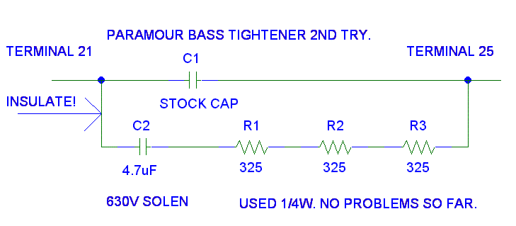
12/06/00: I am considering changing from three to five 325 ohm resistors to bring a little of the bass back while trying not to sacrifice the bass tightness. I have not tried the change yet. I will post both here and on the BBS when I or someone else tries it.
I am going to see if I can scrounge up a larger capacitor. As long as the capacitor draws less than 1.25A, the filament should be OK.
I rms = SQRT( I RMS filament ^2 + I RMS capacitor ^2
I rms = sqrt( 2.5 ^2 + 1.25 ^2 ) = 2.79A (11% more current.)Xc = 2.5V /1.25A = 2 ohms
C = 1/(2 * PI * 60 Hz * 2 ohms) = 1.3 mF = back to back 2200 uF aluminums rated for more than 1.25A each with a little DC bias voltage applied to reduce the aluminum's distortion.Someone asked why add such a big capacitor. With a scope I can see distortion of the 60 Hz waveform on the 2A3's filament. This distortion comes from both the rectified HV winding and the power grid. Hopefully, a large uF aluminum will kill the higher harmonics of this distortion with out adding any new problems.
This mod falls under the "Component Rolling" category. Go ahead and try different values and different manufactures with only two rules:
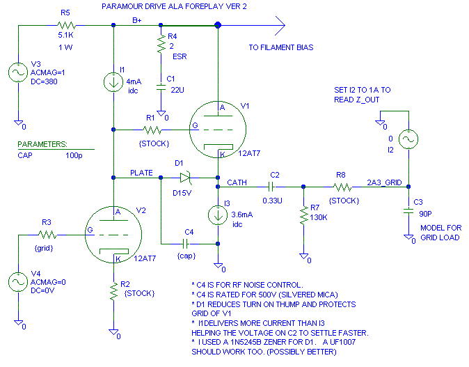
1. Practice safety when working on the amp.I changed the stock capacitor between the SRPP stage and the 2A3 grid to be an Axon 0.33 uF 630V polypropylene and tin foil capacitor. Originally, I just added the new capacitor across the existing capacitor. With the 0.33 uF Axon installed, I think the circuit sounds better with stock capacitor removed.
2. After the parts burn in a little, report your findings on the BBS.
At the same time I installed the new capacitor, I added a 230 K 1/4 W metal film resistor across the existing resistor from the 2A3 grid to ground. The idea behind this was to try to keep the recovery time from supplying 2A3 grid current (due to clipping) reasonably fast with out overloading the SRPP stage. 200 K to 270 K are all acceptable resistor values for this added resistor.
With this change, what I thought I heard was that the bass seemed to pick up a little weight that I lost with the lossy parafeed and I picked up a little better sound stage. I wish I had a second set of Paramours around so I could do a better comparison.
This is how I configured my cathode driver. I don't like the sound at this moment. I am planning on building another 4 mA current source to load the cathode driver (instead of the 45K resistor) to see if it works better. It sounded much better with C2 attached to the plate of the bottom tube instead of the cathode of the top tube.
Note: The 4 mA current source is one of my own design. Link to custom current source, I recommend that you buy a C4S instead.
The good news is that diode from plate to cathode (D1) removed the scary turn on thump that I got when I added the cathode driver. This may be something worth playing with on a Foreplay. As far as I can tell, D1 did not change the sound of the amp.

GOOD NEWS! (01/21/01)
I put a 100 pF 500V mica capacitor from the "Plate" (D1 Anode) connection
to the ground that R2 solders to and the sound greatly improved. 100 pF
may be a bit too much, but it was the smallest I could find in my junk box
stash of parts. 68 pF would probably be a better choice.
I changed R6 (45k 6W) in the sketch above to a 3.6 mA current source.
01/05/01 Update
New idea (19-Sep-01):
I talked with Paul Joppa at VSAC. He suggested trying a larger value
resistor (like a 5K) for R8. This will reduced the control the cathode
follower has on the grid of the 2A3, but it may make things sound better
over all. (not tried as of 19-Sep-01)
A few transformer damping experiments were done on a Paramour. Have a look here: Damping transformers. Some people may notice more of a difference in the sound than I did with the output damped. I decided to not leave the damping parts in my Paramour.
The neatest point of this page is that these same tricks apply to the damping of power transformers and to the damping of interstage transformers. These transformers really need the damping so that they do no overdrive the grid of the stage on the secondary of the transformer.
This I recently did this to a choke (not in the Paramour) and I am giving myself a stupid slap for not doing this on my Paramours. One lead of the plate choke will have more capacitance to the inductor's chassis than the other lead. The lead with the most capacitance to chassis usually should go to B+. Since the inductor frame is usually attached to chassis, this lead arrangement minimizes a "high frequency ground loop" from the plate of the tube through chassis back to the B+'s ground. Beside reducing the ground loop, this arrangement should also minimize the total effective capacitive load the inductor presents to the tube at high frequencies (which is a good thing.)
I did the following with the inductor removed from the chassis:
(If you have two black leads instead of a black and a red lead, mark the leads 1 and 2 with a piece of tape.)
To determine which lead has the most capacitance, drive the inductor with a 1 kHz sinewave (I used 3.8V RMS). Now measure from the ground side of the drive voltage to the frame of the inductor and write the voltage you read down. (With the 1 kHz AC on RED (lead 1) I got 1.289V on the inductor's frame.) Now swap the leads on the inductor and repeat the test. (With 1 kHz AC on Black (lead 2) I got 0.313V on the inductor's frame.) Which ever lead of the inductor that was driven to give the highest AC voltage on the inductor's frame gets attached to B+. (RED, lead 1, goes to B+.)
Note: on the first post of this, the last two sentences did not agree with each other. The words said on thing, the example said something else. I have corrected this error.
This falls under the big bang for the buck category.
I live in a very electronically noisy area.
I have an airport beacon on the hill by my house.All of this electrical noise leads to sonic noise. I put a 0.01 uF 200 V ceramic from pin 13 to 14 in my Paramour and I got an improvement in image and smoothness of the sound. The 0.01 uF 2 kV from Radio Shack will work just as good. Keep the leads short!
I am couple miles from an airport.
I'm a couple miles from an AM radio station.
I'm in a desert with dry sandy soil (lousy earth ground.)
The air conditioner season has started. . . Complain, complain, complain.
What is happening?
Terminal 13 is chassis ground/ safety ground.
Terminal 14 is the signal star ground.
There is parasitic capacitance from the 115V through the power transformer (and elsewhere) to signal ground. This capacitor provides a well controlled location and path for this noise energy to circulate. Ground is funny. It wants to be connected only at one spot at low frequencies. At supersonic to radio frequencies, it wants to be connected everywhere.
I was finding it difficult to exactly null the hum pot. It was difficult to turn it just that little bit to get minimum hum.
Someone posted that they put a knob on the pot to make it easier to adjust. If I find the link back, I'll put it up in the link list so they get credit.
I decided to solder a 15 ohm metal film resistor from the wiper to each end of the hum pot. This is two 15 ohm resistors per hum pot.
This 15 ohm really should be a 1/2 watt resistor, I only had 1/4W 15 ohms in my junk box so I used 1/4W. I measured 1.4V across each 15 ohm resistor which is 0.13W (52% of rated). This corresponds to 2.8V across the filament, remember my line voltage runs high and noisy. Since 1/4W across a 15 ohm resistor is 1.9V, I have to be careful how far I adjust the hum pot.
The hum pot is much easier to adjust now. With Sovtek 2A3s, I can easily adjust to 3 mV rms of hum on each channel. The output hum waveform now looks more sinusoidal. I don't know why. I'm listening to it right now at low levels (so not to wake the rest of the house) and I swear it sounds a little better, a little cleaner. It must be that proud Poppa syndrome we all suffer from occasionally. . .On the other hand, the hum pot is in the audio signal path. . .
xx-Jul-01. I added a small knob on the hum control pot per someone's suggestion on the Bottlehead Forum. This makes adjusting the pot still easier, plus I'm grabbing plastic instead of metal inside all that high voltage stuff! When I find the post back, I'll credit the person who suggested it.
There is another relatively safe way to Parafeed the Paramour that really improves the sound of the amplifier. About a dozen people have tried this so far and they really like it. Click on this link for more details:
The Paramour Parafeed Cathode Mod, the other way to parafeed a Paramour.
Note: Between 23 Sep 01 and 26 Mar 02, Zero people have said they did not like this mod! None of the other mods I've posted have ever done this well.
Soft start/ Active Filter for Paramour
Try this at your own risk.
I have a pair of AVVT cobalt mesh plates I bought for the Paramour. The turn-on of these is scary considering how much these tubes cost. I have only used them once for 4 hours before I went back to the stock 2A3s. The sound was fabulous with the mesh plates. Just so you know. ALL OF THE MODS on this page were done and listened to with the stock tubes. If I use the AVVTs I will say so.
A long long time ago I started a design for a soft start for my Audio Note Kit 4 (6V6 push pull). The design never got built. I used a static sensitive digital counter for the delay (increase the difficult to 5 if these are used.) I am redesigning this soft start/ filter to be all analog for the Paramour. I probably won't have the parts for this until after Christmas. Here is my idea:

I am also working on a BJT version of the above that may work better at higher frequencies than the FET version above. The tradeoff is the FET will work better at low frequencies. I am also considering cascading a FET version with a BJT version.
Update: So far from a couple Pspice runs, the BJT version does not look that promising. R2 and R3 must become lower values and C1 and C2 become much larger values. If there is a tube fault, it does not look like the pass transistors will survive. The BJT version is not out of the running, but the FET version looks like it will be easier, smaller, less expensive and more robust than an all BJT version. I am thinking that a cap from R19 to ground on the "M1" side will solve most of my FET high frequency worries.
Notes: Yes I know I am violating my own large value resistor rule. The 1 meg resistors on C3 will need some sort of conformal coat on them to keep the leakage currents under control. I am concerned that dried clear fingernail polish may be too flammable for this purpose.
 ( New
2024 index page.)
( New
2024 index page.)
 _( Old 2003 index page.)
 _( AMP Second index
page.)
_( AMP Second index
page.)
 ( Fancy index page.)