
These notes and mods are for
the original amp sold in year 2000 ONLY!
I don't have a clue if they will work in the
current production amps.
I don't know how to determine what version amp
you have.
If you break it, you fix it.
The C4S with a resistor in the collector should
work better than this current source, but I'm going to try this anyway.
This design is a two terminal current source with two feedback paths.
The C4S is a three terminal current source (2 active terminals + bias)
without any real feedback.
By the way, I've got it installed in my Paramour and it works! There is increased detail, speed, space and even bass. Pitch definition is much better. The highs are a bit hotter (not harsh) but not annoying so. It may be more accurate to say the highs are not as "soft." There is a slight bit of hiss audible with my ear touching the speaker that was not there before.I had posted earlier that the 2A3 had noise on it's grid that was coming from the 2A3. I knew this because the amplitude of the noise was higher on the 2A3 side of the grid resistor than on the other side. This his could be from the higher output impedance of a current fed 12AT7's plate vs a SRPP (The SRPP has a lower output impedance than a plate alone.)
For B+ I used the 350V I have coming off my Hum and noise reduction circuit. The "unused half" is set up with the grid still connected to the plate of the bottom tube and the cathode going to ground through a 150K 2W resistor. I am sort of looking forward to making two more of these to load this "unused half" and drive it to drive the 2A3 grid.Update (01/14/01)
I put a 1430 ohm resistor across the 169 ohm resistors to raise the current from 3.5 mA to 4.0 mA. I put the new resistor one hole to the right and one hole down from the existing 169 ohm resistor. (I also cleaned it again.)The plate voltage on one amp went up to 171V and on the other amp 155V. It sounded better, but it also rained today so that could have been part of sonic improvement. (Wet soil makes a better ground at the utility panel.)
Pspice test circuit
I've got a bag of 21.0 Ks waiting for a home, so I optimized the circuit for good operation with parts I already have. The circuit takes a bit of work to optimize for other current levels.
To change from 4 mA to 3.0 mA, just about every resistor has to change by a ratio of 4/3 higher. I have just enough MPSA42s to build 4 of these. My actual current was less than 4 mA because the voltage across D1 was low and the voltage across Q1 was low.
* D3 protects the base-emitter of Q1 at power down.
* Q1's collector to base protects Q2's base-emitter at power down.
* D2 protects Q3's base emitter at power down.
* R5 and R6 limit the current into D2 and D3 at power down.
* R3 and R4 reduce the power in Q1 and Q2 by shunting current across
these two transistors into the current set resistor R1 through D1.
* D1, C1 and R2 bias up Q1.
* At low voltage drops across the current source, D1 will not
conduct. C1 insures there is an AC path for the R2 and R4 current
into R1 to keep the impedance of the current source high in all normal
operating conditions.
I measured 3.5 mA with 169 ohms for R1 in the
actual circuit. This was because Vbe of Q1 was 0.575V instead of 0.608V
and the voltage across D1 was a little low. I've calculated that if I
put a 1K across the 169 ohm R1 (for a total of 145 ohms) I'll get 4.0 mA
out. My 12AT7 was running 145V plate voltage at 3.5 mA. 145V is a little
low.
Normally the current source with the hum reduction mode on the B+ will run at 175V to 200V across it. This result in just under 250 mW in each MPSA42 at the 4 mA setting. The MPSA42 derates at 5 mW/ C or 200 C/ W. So the temperature rise on the MPSA42 will be 0.25 W * 200C/ W = 50 C. This is OK for this type of transistor at room temperatures. I would not go higher.

Rout VS frequency. The pair of 715 ohms (R5, R6) kill a potential oscillation at 10 MHz. (I hope.)
The CALCULATED distortion curves for 100 Hz
The Calculated distortion curves for 10 kHz.
This run and the run above have different results based on how I draw
the circuit. Because of this, I don't know how much I would trust the 56
nA of distortion current at 30 kHz. When you run a transient response in
PSpice. Make sure it is for at least 3 cycles. Throw away the first
cycle for it will have a lot of drift in it. The use the last two or
more cycles for the Fourier analysis.
Second cut at layout, top view. It will be very easy to short parts out.
I installed the 680 U 25V last. Before the cap was installed, I scrubbed the heck out of the board with an acid brush and acetone to get all the flux off. I did not want flux messing up the operation of the board. Beware, acetone is extremely flammable.
If this diagram isn't obvious to you and you don't
have an oscilloscope, you're not ready for this difficulty level. Buy a
C4S instead.
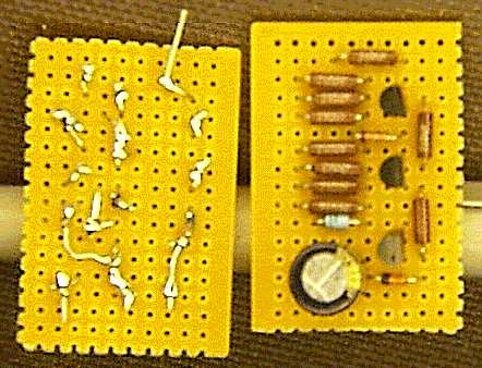
Two of the stuffed boards after cleaning all the flux off. (For the second time.)
I erased the markings off the 1n4148s with the
acetone I used.
 ( New
2024 index page.)
( New
2024 index page.)
 _( Old 2003 index page.)
 _( AMP Second index
page.)
_( AMP Second index
page.)
 ( Fancy index page.)