The other way to Parafeed the
Paramour.
This is a nice mod: not too hard and lots of bang for the buck.
There are really only 2 ways you can Parafeed the stock Paramour:
The stock way
This way.
This involves working with high voltages,
attempt these changes at your own risk.
Unplug the unit from everything, pull the tubes and wait for B+ to
be less than 9V before soldering!
If your output transformer's coil is dented or
nicked up, don't do this mod!!!
Exposure to solvents and water can also damage the magnet wire
insulation in the transformer.
Make the test measurements with care. These tests are to
check the magnet wire insulation.
These notes and mods are for the
original amp sold in year 2000 ONLY!
I don't have a clue if they will work in the
current production amps.
I don't know how to determine what version amp
you have.
If you break it, you fix it.
(9-24-01) Note: If you do this mod, start with version 6A. Then if you
have hum, cut the terminal 12 to 22 jumper in the middle and attach the 2K
resistor used in version 6B to the two dangling leads you just made with
your cutters.
Shopping list:
Version A: 1 foot of insulated wire and
some heatshrink or insulating tape.
Version B: 1/2 foot of insulated wire (or less),
a pair of 2K 1/4W metal film resistors and some heatshrink or
insulating tape.
That's it!
Before we start the mod, we have to check a few
things.
Pick a piece of music with bass and a
vocal. Play it twice listening the pitch of the bass and the clarity of
the vocal. This is your reference. Write down the volume setting you
used when you listened.
With the power on and no input signal, measure and
record:
1. The AC voltage from the black output
terminal and the RCA ground or terminal 14 ground. This should measure
<1.0 V AC. Nearby fluorescent lights will mess up this
measurement.
2. The DC voltage from the black output terminal
and the RCA ground or terminal 14 ground. This should measure much
less than 0.2 V DC.
3. Turn the power off. Wait 10 seconds. Don't
unplug anything yet. Measure the ohms from the black output terminal
and the RCA ground (>1 meg). If you don't measure >1 meg, unplug
the speakers and try again.
Work steps:
4. Unplug the Paramour from everything,
pull the tubes and wait for B+ to discharge to less than 9V.
Put the tubes someplace safe and arrange them so you can get the same
tubes back into the same amplifier (this will make the listening test
comparison a fair as possible.)
4.1 (Added 7-Oct-01) Measure the ohms from
terminal 15 (red lead) to terminal 14 (black lead). Write the number
down. There is a capacitor on terminal 15 that will cause this reading
to move all over the map. It should read greater than 10 k and less
than 300 k. Give it 30 seconds to settle before writing the number
down.
5. Disconnect the transformer connection to
terminal 14 and move it to terminal 11. Don't pull on the transformer
lead to make it fit, that is a good way to ruin your output
transformer. If you break your output transformer, you have to buy a
replacement. This is an unauthorized mod to the Paramour. Neither Doc
nor I warrant this mod.
If you need to make the lead longer, add some
wire and put two layers of heat shrink over the splice. Don't heat up
any of the capacitors when shrinking the heat shrink. Shrink the heat
shrink before you solder to terminal 11.
6. Version 6A is safer than version 6B. If you
have a powered subwoofer running off the speaker outputs, you may want
to consider version 6B if you get hum. If you don't have a powered sub
attached to the speaker outputs, do version 6A.
Version 6A:
Run a wire from terminal 22 to terminal
12. With a wire from 22 to 12 if the transformer fails, the cathode of
the tube will be shorted to ground instead of 60V appearing on the
speaker terminals.
Version 6B:
Leaving the 2K resistor leads fairly long,
connect a 2K resistor from terminal 22 to terminal 12. Sleeve the leads
if you have sleeving laying around. Note: it is OK to solder the
resistor to the resistor lead going to terminal 12. Make sure the
resistor is 1/4 inch from everything. This is your OH SHIT resistor. If
it smokes, the output transformer has a dangerous failure in it and you
hopeful will smell the resistor cook as a warning.
7. Clean all your solder joints with a Qtip (tm)
or industrial cotton swab. Remove any cotton fibers from the
terminals. Don't use any chlorinated solvents to do this. Chlorine
kills aluminum capacitors. Do not spray solvent on the terminals! Put
the solvent on a Qtip (tm) and use it to clean the terminals.
8. Measure 1.0K to 1.4K from terminal 14 to
terminal 11.
8.1 (Added 7-Oct-01) Measure the ohms from
terminal 15 (red lead) to terminal 14 (black lead). Write the number
down. There is a capacitor on terminal 15 that will cause this reading
to move all over the map. It should still read greater than 10 k and
less than 300 k. Give it 30 seconds to settle before writing the
number down. Compare this number to the one you wrote down in step
4.1. It should be close (+/- 30 %) to what you read before.
If this reading is less than 2 k, you
connected 21 to terminal 12 instead of connecting 22 to terminal 12.
9. Measure <1 ohm from terminal 14 to terminal
12.
10.
If you did version 6A, measure <1 ohm from terminal 14 to the black
speaker terminal.
If you did version 6B, measure 1.9K to 2.1K from terminal 14 to the
black speaker terminal.
With the power off and the unit unplugged put
your tubes back in and attach:
The black lead of your meter to terminal
14 and
the red meter lead to the black speaker terminal .
With the power on and no input signal,
measure and record:
11. The AC voltage from the
black output terminal and the RCA ground or terminal 14 ground. This
should measure 0.000V to 0.5V greater than what you read in step 1.
Remember, nearby fluorescent lights and noise
sources will mess up this measurement.
12. The DC voltage from the black
output terminal and the RCA ground or terminal 14 ground. This
should measure zero to no more than what you read in step 2.
If you fail steps 11 or 12. Check your work.
Step 11 is easy to fail because of noise pick up. Step 12 is
critical to pass. Step 12 verifies your transformer insulation.
If the black speaker terminal measures about
60V, the wire you added from terminal 22 probably is attached to
terminal 11 (wrong) instead of terminal 12 (right).
13. Breath for a second or two.
14. Turn the unit off, wait for the capacitors
to bleed down and move your DVM to be across terminal 14 to A4.
(Black to 14) Turn the unit back on and verify that A4 is about 60 V
DC. Once you verify the voltage, turn the amp back off, wait
for the voltages to bleed down and remove the DVM from the amp.
15. Put the amp back in your system and go
listen at the same volume that you did before with the same CD. The
midrange gain of the amp should not have changed!
What did we just do?!
We returned the AC current from the output
transformer to the cathode of the 2A3. This helps to make the sound of
the cathode capacitor disappear! I've got the scope photos below to show
that this actually works. Now all the cathode capacitor has to
filter is changes in the bias current, not changes from driving the
speaker. We still need a capacitor on the cathode for bias stability and
to handle tube parasitics, but now the sound of the capacitor is not a
big issue.
Why can we get away with this with a inexpensive
output transformer?
Undamaged magnet wire that is wound on a
transformer bobbin can easily support the 60V DC from cathode to ground.
The magnet wire in the output transformer is protected from abuse if the
transformer has not been scratched up, nicked up or dropped. If the
magnet wire is nicked up, scraped or dented, the insulation no longer
reliable and we can't trust 60V across it.
If your output transformer's coil is dented
or nicked up, don't do this mod!!!
NOTE:
Do not even think about
attaching the stock transformer to the plate of the 2A3 and putting
the capacitor in the ground leg!
The stock transformer does not
have supplemental insulation nor creepage to block the high
voltage.
Attaching the stock
transformer to the plate of the 2A3 is a way to get seriously
hurt! The stock transformer cannot support B+ for more than a
short period of time! Do not earn a Darwin award by doing this
"hot transformer" version of parafeeding!
As of 9/16/01 I only have one channel modified in my Paramours. Comparing
the modified channel to the unmodified channel is revealing! This mod
kicks butt!
I am hearing deeper cleaner bass with just one
amplifier modified. This midrange is smoother and occurs with an ease I
did not know I was missing until I went to VSAC and heard the Paraglow
2A3 amps.
Unfortunately, I was too tired to do the
other channel right (on the 16th.)
On 9/17/01 I had two Paramours modified.
The bass was clean and deep. The midrange was
effortless. Most of all, the stereo image improved!
Wow! These improvements are definitely not a case of proud poppa
syndrome. This change sounds great!
On 9/23/01 Anand tried this out. Anand (a New Yorker) says "It sounds like
butter."
Thanks to Anand for being my guinea pig and finding
a significant typo!
Scope Photos from VoltSecond's
Paramour Before and After the Change
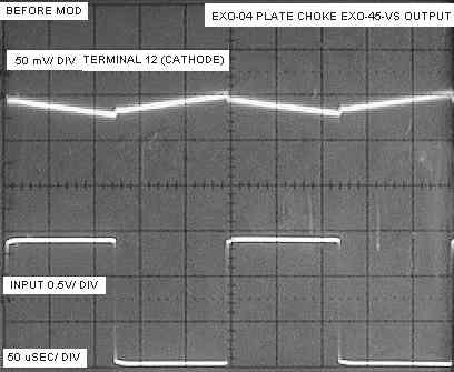
This is what the voltage on A4 (terminal 11) looks
like before the modification with a 40 Hz input squarewave.
My squarewave generator has a DC offset so I added a capacitor in series
with it to remove the DC offset. That is why the input square wave is
sloped.
Note: A 0.33 uF AXON capacitor is driving grid of 2A3 with 130K ohms to
ground from the grid of the 2A3.

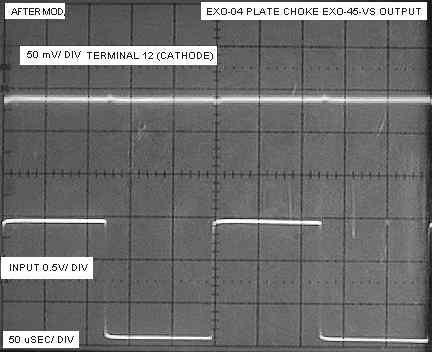
Notice that not only did the amplitude on the cathode of the 2A3
decrease, almost all of the high frequency modulation (bad) on the
cathode is gone. (Note: The "after" picture is a composite of two
pictures pasted together to get one complete sweep.)
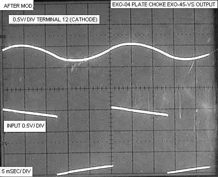
Now lets drive it with about 4 kHz. I'll turn the
trace gain up a factor of 10 on the cathode trace.
Wow! I suspect that the little bumps in the cathode trace in the after
picture are from winding to winding capacitance in the output
transformer. The winding to winding capacitance does not get circulated
through the cathode capacitor.
I repeated the above 4 kHz pictures on my second
Paramour, but this time used a 1:1 probe on the 2A3 cathode so I could
display 5 mV/ div.

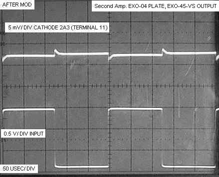
This is simply awesome that for once, something that sounds better
actually looks better when checking it using a scope.
If I get ambitious, I'll add some Pspice pictures.
I think the scope photo's of the cathode voltage tell the technical part
of the story quite well.
Schematically, this is what we are doing. The numbers in the circles are
the terminal numbers from the 2000 model year amp.
Damping_ringing_in_xfmrs
.
First version 09/16/01. Last change 09/23/01
9/24/01 added suggestion to start with 6A. Changed from zero to 0.000V
on final AC test.
9/30/01 added reminder to re-install tubes and that the A4 test is DC
not AC.
10/7/01 added resistance check for short to terminal 21. Added schematic
of the change..

 _
_
