This page is: "1. Paramour: Top Level Link. 10% Distortion Tables vs Frequency. Output impedance vs Frequency."
This involves working with high voltages,
attempt these changes at your own risk.
Many people refer to magnetics as
"iron" no matter what the magnetics are made of.
1. Paramour: Top Level Link.
10%
Distortion Tables vs Frequency. Output impedance vs Frequency.
2.
Paramour: Stock Output Transformer, Stock Choke, AVVT 2A3 M
tubes,
Right
Amp, 10% distortion pictures, No distortion curves.
This link opens a new window so you can compare it to other pages.
3. Paramour: Stock
Output Transformer, EXO-04 Choke, AVVT
2A3 M tubes,
Right
Amp, 10% distortion pictures, distortion curves.
4. Paramour: Stock Output
Transformer, Stock Choke, Sino 2A3 tubes,
Left
Amp, 10% distortion pictures, distortion curves and many other
pictures.
5. Paramour: Stock
Output Transformer, Stock Choke, AVVT 2A3 tubes,
Left
Amp, 10% distortion pictures, distortion curves.
6. Paramour:
EXO-45-VS Output Transformer, Stock Choke, AVVT 2A3 tubes,
Left
Amp, 10% distortion pictures, distortion curves,
50
Hz 100 Hz distortion curve comparison.
7. Paramour:
EXO-45-VS Output Transformer, EXO-04 Choke, AVVT 2A3 tubes
Right
Amp, 10% distortion pictures, distortion curves. Final Listening notes.
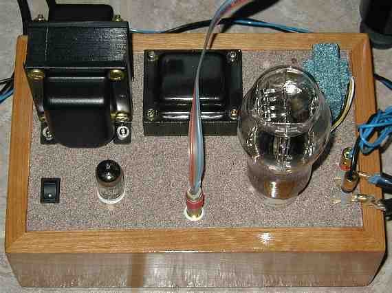
The first version of this mod I implemented is more expensive than it needed to be. I ordered and used an EXO-04 60 mA, 50H, 317 ohms DCR, black bell ends at $198 pr for the plate choke instead of the stock 10H choke. After I had my "iron" in hand, I talked with Mike LaFevre and Paul Joppa more about the choice of iron. I believe a BCP-15 50 ma, 40H, 550 ohms DCR, channel frame at $90 pr would do this job just fine.
The EXO-04 has a slightly lower voltage drop than the BCP-15 (11.7V less out of 360V at 50 mA). The EXO-04 has a little more inductance and the EXO-04 is rated for more current than we will be using through it. These small differences should not make a difference in the Paramour.
The EXO-04 requires drilling 4 new mounting holes plus one larger hole for wires into the chassis plate of the Paramour. Don't try to route the wires through the existing holes in the chassis. I tried it and ended up cutting through the leads and shorting both of them to chassis. Mr. Ohm Meter saved me from making smoke because I measured ohms from chassis to B+ and from signal ground to B+. Make sure you route the wires through a grommet so the edges of the chassis do not cut into the wire insulation. The fifth hole needs to be directly under the hole of the EXO-04 that the leads come out of.
Note: I've been told that the BCP-15 should physically be a drop in replacement for the stock inductor. I have not personally tried the BCP-15 in the Paramour, but the information came from a reliable source.
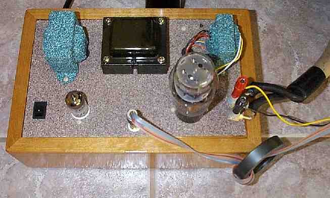
Paramour Stock (left amplifier):
Paramour with EXO-04 Plate Choke (right amplifier):
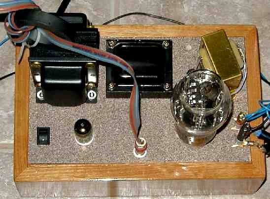
Adding an EXO-45-VS 5K:8 Output transformer:
This transformer was a semi-custom order from Mike LaFevre at Magnequest. The -VS suffix is in my honor (VS = VoltSecond.)
I wanted to stay with a 4K to 5K load on the plate with an 8 ohm output. This EXO-45-VS is a beefed up version of the EXO-45 2W transformer. It uses a 25% larger stack of M4 steel instead of the original size stack of nickel to pick up more capability in the bass.
The EXO-45-VS fits on existing holes in the chassis. I played with different locations with a scope monitoring the primary winding and the best location had the transformer falling off the chassis. The final location was only 25% worse than the best location and used existing chassis holes (hot damn, no drilling!) The transformer got noisier rapidly as it was brought nearer to the power transformer.
Paramour with EXO-45-VS output transformer (left amplifier).

Paramour with EXO-04 Plate Choke and EXO-45-VS output transformer
(right amplifier):
Other Notes:
The first amplifier I modified was the right channel amplifier. If you see "(Right amp)" or "(Right amplifier)" in the notes, this means I was taking readings off the right channel amplifier. The Paramour I am playing with is not stock. Of the other mods I have done, I believe the "Lossy Parafeed" mod and the "Ala Foreplay" driver mod may affect the distortion readings the most.
This is the Lossy Parafeed mod that is in the Paramours being tested:
This is the driver I used in the Paramour when I did the testing shown
on this web page.
The following readings are made at the 8 ohm output terminals of the Paramour with a 8.45 ohm, 200W chassis mount resistor resistive load.
The distortion readings are not exact. My Heathkit sinewave generator's output pot is sticky and won't make fine adjustments. To take these readings I have to set the reference level of the distortion analyzer, null the analyzer, read the distortion, adjust the level of the oscillator and start over at setting the reference level of the HP334A distortion analyzer. After about 5 to 10 iterations, I would take the readings and pictures.
We can see that with a constant distortion level, higher plate inductance gives more output power at low frequencies. The higher plate inductance does not change the output power at high frequencies. I used 10% for these test points because that is where the distortion was easiest to see in the pictures and because anything lower was a bear to read (remember, I'm doing this to relax.) 10% distortion also makes what the iron is doing much more visible than at lower drive levels. These pages are about the iron, not the tube.
Table 1: Output Watts for a given distortion into 8.45 ohms
The Paramour being tested had a 4.7 uF with a series 975 ohms lossy
parafeed mod installed.
| Frequency | Paramour AVVT 2A3 (Right amp) Stock Choke Stock XFMR 10% distortion |
Paramour AVVT 2A3 (Right amp) EXO-04 Plate Choke Stock Output XFMR 10% distortion |
Paramour SINO 2A3 (Left amp) Stock Choke Stock XFMR 10% distortion |
Paramour AVVT 2A3 (Left amp) Stock Choke Stock XFMR 10% distortion |
Paramour AVVT 2A3 (Left amp) Stock Choke EXO-45-VS XFMR 10% distortion |
Paramour AVVT 2A3 (Right amp) EXO-04 Choke EXO-45-VS XFMR 10% distortion |
| 20 Hz | 0.31 W | 0.50 W | 0.29 W | 0.23 W | 0.37 W | 3.71 W |
| 50 Hz | 1.99 W | 3.86 W | 1.72 W | 1.72 W | 2.44 W | 5.08 W (1) |
| 100 Hz | 3.84 W | 4.40 W | 3.26 W | 3.11 W | 3.97 W | 5.46 W |
| 1 kHz | 5.25 W | 5.44 W | 4.65 W | 4.40 W | 4.94 W | 5.70 W |
| 10 kHz | 5.3 W | 5.5 W | 4.7 W | 4.4 W | 4.8 W | 5.47 W (2) |
Table 2: Volts RMS for a given distortion into 8.45 ohms
The Paramour being tested had a 4.7 uF with a series 975 ohms lossy
parafeed mod installed.
(This is the same data as is in Table 1, just in volts instead of
watts.)
| Frequency | Paramour AVVT 2A3 (Right amp) Stock Choke Stock XFMR 10% distortion |
Paramour AVVT 2A3 (Right amp) EXO-04 Plate Choke Stock Output XFMR 10% distortion |
Paramour SINO 2A3 (Left amp) Stock Choke Stock XFMR 10% distortion |
Paramour AVVT 2A3 (Left amp) Stock Choke Stock XFMR 10% distortion |
Paramour AVVT 2A3 (Left amp) Stock Choke EXO-45-VS XFMR 10% distortion |
Paramour AVVT 2A3 (Right amp) EXO-04 Choke EXO-45-VS XFMR 10% distortion |
| 20 Hz | 1.63 V rms | 2.05 V rms | 1.57 V rms | 1.40 V rms | 1.78 V rms | 5.60 V rms |
| 50 Hz | 4.10 V rms | 5.71 V rms | 3.81 V rms | 3.81 V rms | 4.54 V rms | 6.55 V rms (1) |
| 100 Hz | 5.70 V rms | 6.10 V rms | 5.25 V rms | 5.13 V rms | 5.79 V rms | 6.79 V rms |
| 1 kHz | 6.66 V rms | 6.78 V rms | 6.27 V rms | 6.10 V rms | 6.46 V rms | 6.94 V rms |
| 10 kHz | 6.7 V rms | 6.8 V rms | 6.3 V rms | 6.1 V rms | 6.4 V rms | 6.8 V rms (2) |
Table 3: Paramour R_out
The Paramour being tested had a 4.7 uF with a series 975 ohms lossy
parafeed mod installed.
My estimate is that these values need to change by 20% to be audible.
| Frequency | Z_out
8 ohm tap Stock Choke Stock AVVT 2A3 Right Amp |
Z_out
8 ohm tap EXO-04 Choke Stock AVVT 2A3 Right Amp |
Z_out
8 ohm tap Stock Choke Stock Sino 2A3 Left Amp |
Z_out 8 ohm tap Stock Choke Stock AVVT 2A3 Left Amp |
Z_out
8 ohm tap Stock Choke EXO-45-VS AVVT 2A3 Left Amp |
Z_out
8 ohm tap EXO-04 Choke EXO-45-VS AVVT 2A3 Right Amp |
|
20
Hz
|
3.9
|
4.8
|
4.1
|
3.9
|
2.9
|
3.5
|
|
50
Hz
|
3.9
|
4.0
|
3.8
|
4.3
|
3.2
|
3.2
|
|
100
Hz
|
3.7
|
3.6
|
3.6
|
4.2
|
3.1
|
3.0
|
|
1000
Hz
|
3.5
|
3.4
|
3.3
|
4.1
|
2.9
|
2.7
|
|
10000
Hz
|
4.4
|
4.3
|
4.3
|
5.3
|
3.2
|
3.0
|
1. There are complicated ways to describe the distortions in the pictures in this group of web sites that relate to load lines, saturation of output transformers, plate choke inductors running dry (out of current) etc. that I'll get to these much much later after I have them figured out.
2. Better test gear makes better measurements. Better test gear does not make better sound. (I wish I had better test gear! Santa, are you listening?)
Stock magnetics with an AVVT 2A3 compared with aNow that I've had a little burn in time with the EXO-04, I moved my speakers side by side and did some almost mono listening comparisons. Instead of two speaker
Stock Output transformer, EXO-04 plate choke and an AVVT 2A3 output tube.
The Paramour with the EXO-04 had more resolution, had deeper bass and was smoother than the stock Paramour. Piano notes and percussion had a more definite and cleaner "start" to each note.
5/06/01 Measurement notes:
EXO-45-VS Output, Stock Plate Choke and an an AVVT 2A3 compared with aThe EXO-45-VS (5K:8 EXO-45 winding with 1 inch stack of M4 for the iron) initially does not cause as much of an improvement in the sound (after 3 CDs i.e. no burn in) as the EXO-04 plate choke did. However, the 20 Hz overload characteristics are pretty to look at! The waveform decays smoothly like an LR filter with no extra nasties. I've been warned that the EXO-45 takes 50 - 60 hours of music to break them in. I'll post more after they break in.
Stock Output transformer, EXO-04 plate choke and an AVVT 2A3 output tube.
All the measurements so far were taken with a flaky Heathkit IG-5282 sine generator. I have fixed two of the sine generator's problems.
First the 9V batteries were dropping to 8V under load (they measured 9V unloaded). New batteries fixed that.I will retake the right and left channel distortion measurements in the near future. The output impedance and distortion pictures won't change because of this mod so I'm not going to retake those pictures. Note that the output power did not significantly change with the new output transformer, but I took about an ohm off the output impedance.Second the amplitude adjust pot will not make fine adjustments. I changed the original "1K series resistor feeding a 1T 10K pot" out with a "3K resistor feeding a 2K 5 turn pot".
Go to page 7 for final listening notes.
.First version Apr 13, 2001 Last change 05/25/01 - VoltSecond
.
 ( New
2024 index page.)
( New
2024 index page.)
 _( Old 2003 index page.)
 _( AMP Second index
page.)
_( AMP Second index
page.)
 ( Fancy index page.)