This page is: "2. Paramour: Stock Output Transformer,
Stock Choke, AVVT 2A3 M tubes,
Right Amp, 10% distortion pictures, No distortion curves. (Opens a
new browser window.)"
This involves working with high voltages,
attempt these changes at your own risk.
Many people refer to magnetics as
"iron" no matter what the magnetics are made of.
1. Paramour: Top Level Link.
10%
Distortion Tables vs Frequency. Output impedance vs Frequency.
2.
Paramour: Stock Output Transformer, Stock Choke, AVVT 2A3 M
tubes,
Right
Amp, 10% distortion pictures, No distortion curves.
This link opens a new window so you can compare it to other pages.
3. Paramour: Stock
Output Transformer, EXO-04 Choke, AVVT
2A3 M tubes,
Right
Amp, 10% distortion pictures, distortion curves.
4. Paramour: Stock Output
Transformer, Stock Choke, Sino 2A3 tubes,
Left
Amp, 10% distortion pictures, distortion curves and pictures.
5. Paramour: Stock
Output Transformer, Stock Choke, AVVT 2A3 tubes,
Left
Amp, 10% distortion pictures, distortion curves.
6. Paramour:
EXO-45-VS Output Transformer, Stock Choke, AVVT 2A3 tubes,
Left
Amp, 10% distortion pictures, distortion curves,
50
Hz 100 Hz distortion curve comparison.
7. Paramour:
EXO-45-VS Output Transformer, EXO-04 Choke, AVVT 2A3 tubes
Right
Amp, 10% distortion pictures, distortion curves.
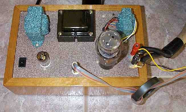
Stock Output Transformer
Stock Plate Choke
AVVT 2A3 M tubes.
Pictures are taken at 10% distortion into 8.45 ohms
at the 8 ohm speaker output (Right Amplifier).
An old HP 334A was used to measure the distortion.
Added 04/13/01 Updated 04/13/01
Left Paramour shown with Sino 2A3
for reference.
This is with the stock Paramour magnetics at 10 kHz, 2V/ div, 10 usec/
div, 10% distortion. The bottom of the waveform is clean. The top of the
waveform is clipped because the tube ran out of what I am calling "voltage
headroom." If I reduce the amplitude of the output, the waveshape becomes
a plane old boring clean sinewave. Do you really need to see a plain old
clean sinewave? ;-)

This is with the stock Paramour magnetics at 1 kHz, 2V/ div, 100 usec/
div, 10% distortion. Note: The bottom of the waveform is clean.

This is with the stock Paramour magnetics at 1 kHz, 5V/
div, 100 usec/ div, 10% distortion. This is the same test point as the
picture above with a different voltage scale. This is just to show you
that the bottom of the waveform actually is clean. The slight distortion
on the bottom of the waveform is more from my Heath Kit sinewave generator
than from the power amp. This waveform represents the tube running out of
voltage to drive the output transformer.

This is with the stock Paramour magnetics at 100 Hz, 2V/ div, 1 msec/ div, 10% distortion. You can see that the distortion is different. A simple explanation of what is happening here is the plate choke and tube are running out of current to drive the output. When this happens, the output voltage sags instead of clipping.
Is this a load line problem with the tube? Is this a phase shift problem?
I am not sure what the best way is to describe the problem. Lets just use
the simple explanation for now.

This is with the stock Paramour magnetics at 50 Hz, 2V/ div, 2 msec/ div,
10% distortion. Same story as at 100 Hz.

This is with the stock Paramour magnetics at 20 Hz, 2V/ div, 5 msec/ div,
10% distortion. This image is a composite of multiple digital pictures
because my digital camera only caught parts of the waveform in the 12
shots I took.

 ( New
2024 index page.)
( New
2024 index page.)
 _( Old 2003 index page.)
 _( AMP Second index
page.)
_( AMP Second index
page.)
 ( Fancy index page.)