
Inverse Single Series Single Shunt Stepped Attenuator
WITH A SHARED L-PAD FOR THE LAST FEW SWITCH STEPS
A Design With No Switching Pops!
-----------------------------------------------------------------------------------
The Single Series Single Shunt Stepped Attenuator shown below on the bottom right has a problem in that it needs a good Make Before Break switch, or you'll get loud "pops" when changing the volume level. The DIY community found that putting multiple stacks of switches in parallel will solve the "popping" problem. Only the switches are ganged up, there is still 1 set of resistors needed For more about this, see the 12 Position Shunt Regulator webpage from a long time ago that discusses these older style of attenuators.
From my old attenuator website:
Figure 1.0 Six
Ways to Make an Attenuation
(There are many more than six ways!)
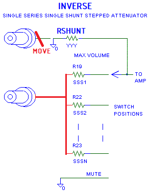
In this new design, let's use a different switch, a Break Before Make switch. With a Break Before Make contact, what we will want is a way to make the volume go to "zero" when the attenuator switches open up between contacts. All that takes is for the wiper to go to the amps input with the wiper having a resistor to ground.
Below I show the changes to the design. The resistors that used to go to ground now go to the input signal. The resistor that went to the input signal now goes to ground. At first look this is simple, we flip the position of the signal and ground in the stepped attenuator, then we can get by using a more common Break Before Make switch. Unfortunately, we'll have to change all the resistor values when we do this. If building one, it would be best to start with a new 12 position switch and new resistors and not re-used the existing attenuator.
With this topology, we have to pick
the shunt resistor to ground to be the lowest impedance we wish to load
the signal source with. The lower we make this value, the more
reasonable the values of the resistor will be. If the source is
solid-state, dropping R_Shunt down to 5k ohm would be OK. With a tube
source, we should keep this minimum impedance above 20K, if not 50K or
even 100K. With the higher R_Shunt impedances, to get high attenuation,
we'll need ridiculously high values for the other resistors.
When I released my older webpage on the 12 Position Shunt Regulator, I was asked why I didn't include this seventh method as an attenuator option. I responded that the resistor values got ridiculous pretty fast, and I didn't search further for a solution. I've had problems with 221K 1% resistors in that the value was not "1%" when the humidity was high enough for condensation to start and the part was used at far less than 1/2 rated power. I've also had issues with fingerprints changing the value of a 1 meg resistor more than 1%, over time, even in a dry environment. Normally we want to minimize the use of precision values higher than 500K ohm if the part isn't running warm (>=1/2 rated power) if it is at all possible. Fortunately, I've recently had an "Aha!" moment and smacked my forehead because the solution is simple.
The math for a resistive divider is as follows:
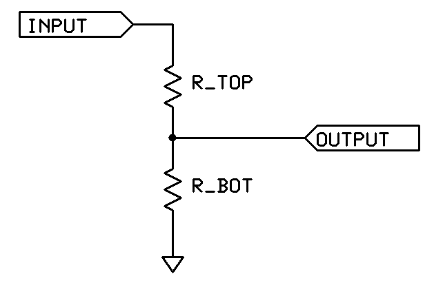
Gain = R_Bottom / (R_Bottom + R_Top) (Equation 1)
Gain in dB = 20 Log (Gain) (Input and output Impedances must stay constant.)
Attenuation is when the gain is less than 1 in the "linear world". In the world of "dB", attenuation is when the gain is negative. For example, a gain of 2 expressed in dB is 20 log 2 which gives +6.02 dB and gain of 0.5 is 20 log 0.5 which gives -6.02 dB.
Re-Arranging Equation 1 to get our resistor selection formulas:
Top_R = Bottom_R/Gain (Linear) - Bottom_R
Bot_R = Top_R * Gain/(1-Gain)
Bot_R = Gain * R_Total
Lets use the math for a resistive divider with -6.02dB gain. This is a linear gain of 0.5 or half voltage.
Let's say R_Bottom is 100K, what does R_Top need to be?
R_Top = 100K/0.5 - 100K = 200K - 100K = 100K (Not a bad value and the math works).
For 50dB attenuation (-50 dB gain) and a bottom resistor of 100K, the linear gain is 3.16e-3 we need a top resistor of:
R_Top = 100K/3.16E-3 - 100K = 31.6meg ohm - 100K = 31.5meg ohm (Yikes! That is not a friendly value.)
The "Aha" is that to get around the issue of insanely high resistor values, we can add a divider in front of the switch to get the additional attenuation we want.
One way is shown in my old webpage's Figure 7.1: T-PAD:
RT1 and RT2 make a resistive divider.
Adding RT3 lets us raise the divider's Thevenin output impedance.
RT4 becomes our R_Shunt for more attenuation.
A 20dB
attenuation example:
The first 14.2 dB comes from RT2 and RT1. (20K/(20K+82.5K) = 0.1951 = -14.2dB )
R_out of the first divider = 1/ (1/RT2 + 1/RT1) = 16.1K ohm. Then we add RT3, 82.5K to R_out for 98.6K ohm total.
The
second 6 dB comes from the 100k (98.6k) output impedance of the T pad
and the 100K volume pot.
14 dB + 6 dB = 20 dB total attenuation (-20dB gain)
TANSTAAFV, in this new topology RT1 ends up in parallel with R_SHUNT. However, if RT1 is 10X or higher than R_Shunt, the minimum input impedance of the attenuator design doesn't change that much.
[
"There Ain't No Such Thing As A Free Variable", but some are pretty
cheap. ]
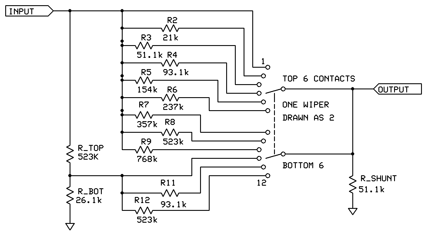
In an example 12-step build, the attenuator looks like as shown below. When the "wiper contact" goes open, we have R_Shunt to ground resulting in no signal going through from input to output and our amplifier's input still having a DC resistance to ground to prevent bias shifts. These two features causes the "Pop" when changing volume to be eliminated.
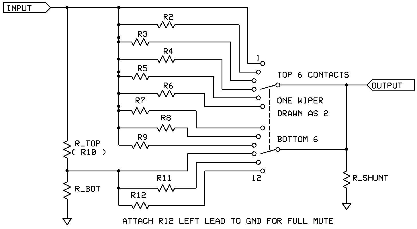
The input L-Pad made by R_Top/R_Bot will be in parallel with R_Shunt in steps 1-9. When picking R_Shunt, round it up in value to keep the minimum input impedance above your desired minimum.
Step 1 is 0 dB attenuation, R1 would normally be set to zero.
Step 2 through 9 adds a single resistor in series with R_Shunt to change the volume.
In Step 10 we cheat, we set up a new voltage divider to provide this gain level. I normally would make R_Top the same value as R8 or R9 and make R_Bot the same value as R3 or R4. If I were to add a new value resistor to the parts list, I'd make R_Bot the new value.
Step 11 we add a resistor in series with the divider to get more attenuation.
Step 12. We have a choice. We can either connect R12 to signal ground for a full MUTE, or we could use R12 to give us an additional volume step. I very seldom use the "Mute" option and if I really need a "Mute" I pause the music source. I would pick R12 to provide a 10 to 20dB step of more attenuation.
The input L-Pad doesn't just have to be restricted to going to steps 10, 11 and 12. It could go to just step 12, or it could start at step 7. It all depends on the step size and minimum input impedance you are picking. I ran a couple versions of this design through the spreadsheet and attaching the L-Pad at step 10 worked the best for me.
If you want to use a 24 position switch, you could split R_Bot into two series values to make for a larger range of attenuation. If R_Bot were 20K, adding a 681 ohm under it will start a series of "taps" with 30dB more attenuation that the 20K already provided.
The only time I would use 1dB steps is when I'm matching volumes for comparing amps or speakers. I would not use 1dB steps to balance the left and right channels. If the left to right balance isn't right, something is broken in the audio chain. I'd fix what was broken.
I've lived with 3dB steps and 3dB steps are fine. If I wanted a 1.5 dB step, I'd add a 1.5dB L-Pad after R_Shunt before the output signal went to the rest of the circuitry.
The original step sizes from the S4 stepped attenuator I put in my Bottlehead Foreplay are shown below in Table 2.2: 20 K Series, Single Shunt Stepped Attenuation (-1 to -40 dB) from my old web page.
(Note: These 20K values are the values I used in my Bottlehead Foreplay attenuator.)
|
|
Resistor Value to Selector: |
20.0k |
Step Size |
|
22.1k |
Delta to 20.0k |
|
47.0k |
Step Size |
|
200k |
|
487k |
Step Size |
|
Position |
Closest Michael Percy Catalog Value |
dB |
dB |
|
dB |
dB |
|
dB |
dB |
|
dB |
|
dB |
dB for 487k |
|
1 |
165.K |
- 1.0 |
3.02 |
|
- 1.1 |
-0.1 |
|
- 2.2 |
5.3 |
|
- 6.9 |
|
-11.9 |
11.8 |
|
2 |
34.0K |
- 4.0 |
2.97 |
|
- 4.3 |
-0.3 |
|
- 7.5 |
4.3 |
|
-16.8 |
|
-23.7 |
6.1 |
|
3 |
16.2K |
- 7.0 |
2.98 |
|
- 7.5 |
-0.5 |
|
-11.8 |
3.8 |
|
-22.5 |
|
-29.8 |
4.7 |
|
4 |
9310 |
-10.0 |
3.05 |
|
-10.6 |
-0.6 |
|
-15.6 |
3.6 |
|
-27.0 |
|
-34.5 |
4.1 |
|
5 |
5760 |
-13.0 |
3.04 |
|
-13.7 |
-0.7 |
|
-19.2 |
3.4 |
|
-31.1 |
|
-38.6 |
3.7 |
|
6 |
3740 |
-16.1 |
2.88 |
|
-16.8 |
-0.7 |
|
-22.6 |
3.2 |
|
-34.7 |
|
-42.4 |
3.3 |
|
7 |
2550 |
-18.9 |
3.00 |
|
-19.7 |
-0.8 |
|
-25.8 |
3.1 |
|
-38.0 |
|
-45.7 |
3.3 |
|
8 |
1740 |
-21.9 |
2.94 |
|
-22.7 |
-0.8 |
|
-28.9 |
3.1 |
|
-41.3 |
|
-49.0 |
3.1 |
|
9 |
1210 |
-24.9 |
6.18 |
|
-25.7 |
-0.8 |
|
-32.0 |
6.3 |
|
-44.4 |
|
-52.1 |
6.4 |
|
10 |
576 |
-31.1 |
9.03 |
|
-31.9 |
-0.8 |
|
-38.3 |
9.2 |
|
-50.8 |
|
-58.6 |
9.2 |
|
11 |
200 |
-40.1 |
N/A |
|
-40.9 |
-0.9 |
|
-47.5 |
N/A |
|
-60.0 |
|
-67.7 |
N/A |
|
12 |
0 |
MUTE |
|
|
MUTE |
|
|
MUTE |
|
|
MUTE |
|
MUTE |
|
Notes:
1. Something like the stepped attenuator above, but quite a bit fancier,
appeared in Audio Amateur years ago.
2. Position 10 is purposely a 6 dB step with a 20 k input.
3. Position 11 is purposely a 9 dB step with a 20 k input.
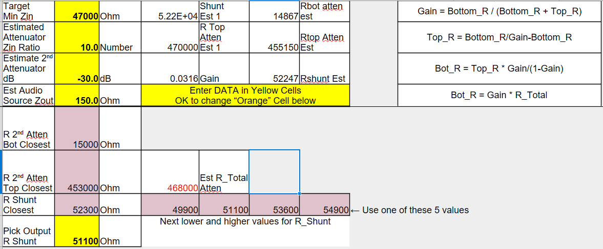
Lets design a 47K minimum input impedance attenuator. We want 3dB steps except for last three positions where we want something close to 6 to 10dB steps.
47000 ohm or 47E3 for the target min Zin,
10 for the impedance ratio of Rshunt to Rdivider (we'll fine tune this later.)
-30 for ESTIMATED gain of the voltage divider (we'll fine tune this later.)
The source impedance of the most used signal source, say 150 ohms from a CD player.
The spreadsheet will recommend 5 values for the Actual R_shunt. 52300 ohms is best, but I normally use 51.1K in my designs so. . .
51100 ohms is entered for R_Shunt
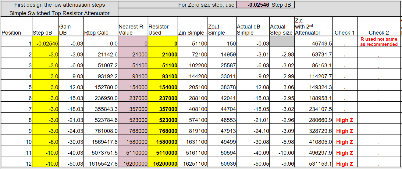
Pick your step sizes first. The first step will need to be around -0.025 dB to keep the 150 ohm "Zout" of your signal source from causing "divide by zero errors" in the spreadsheet. Up on the top of the input area, the actual value you need to enter for "Zero" is already calculated and is shown with a purple background.
You don't have to use the nearest value calculated for the series resistors, but in the example I did.
You can see that at step 8 the impedances start to get high and at step 10 they are too high for comfort. Really! ;-) In Step 12, what is this 16 gigaohm? ;-) That has to be higher than what you get when you measure across the clean side of the wax paper the sub-shop wraped your lunch in.
The actual step sizes in dB don't exactly match what we wanted. This is because we are using standard 1% resistor values and not building custom values with parallel/series resistors.
Then pick the parts for the L-Pad and for the switch positions after the "L-Pad" voltage divider.
The spreadsheet recommended we use 453K for R_Top. We're going to use 523K because we'll already be buying that value for switch position "8".
Enter 523000 in the Orange Cell (or point it to the cell above with 523000 in it).
For R_Bot, we have to round up from the exact value calculated for R_Bot to a standard resistor value. The calculations will show math errors if we round down. That is why the value in "Rbot Step 2 Single R Calc" is 1.012 times higher than the exact value. After rounding up, 26100 ohms ends up being recommended. I looked at what 21K and 51.1K do because we are already using those values, but I didn't like the results. So we'll use a new value, 26.1K, in the Yellow Cell
Enter 26100 in the top Yellow Cell for the Bottom R.
For position 11 and 12, I used values already in use. I didn't get the two 10 dB steps I originally wanted, but the 6.9 (7) dB step and an 11 dB step I got were good enough. In the yellow boxes:
Enter 0 for position 10
Enter 93.1E3 for position 11
Enter 523E3 for position 12
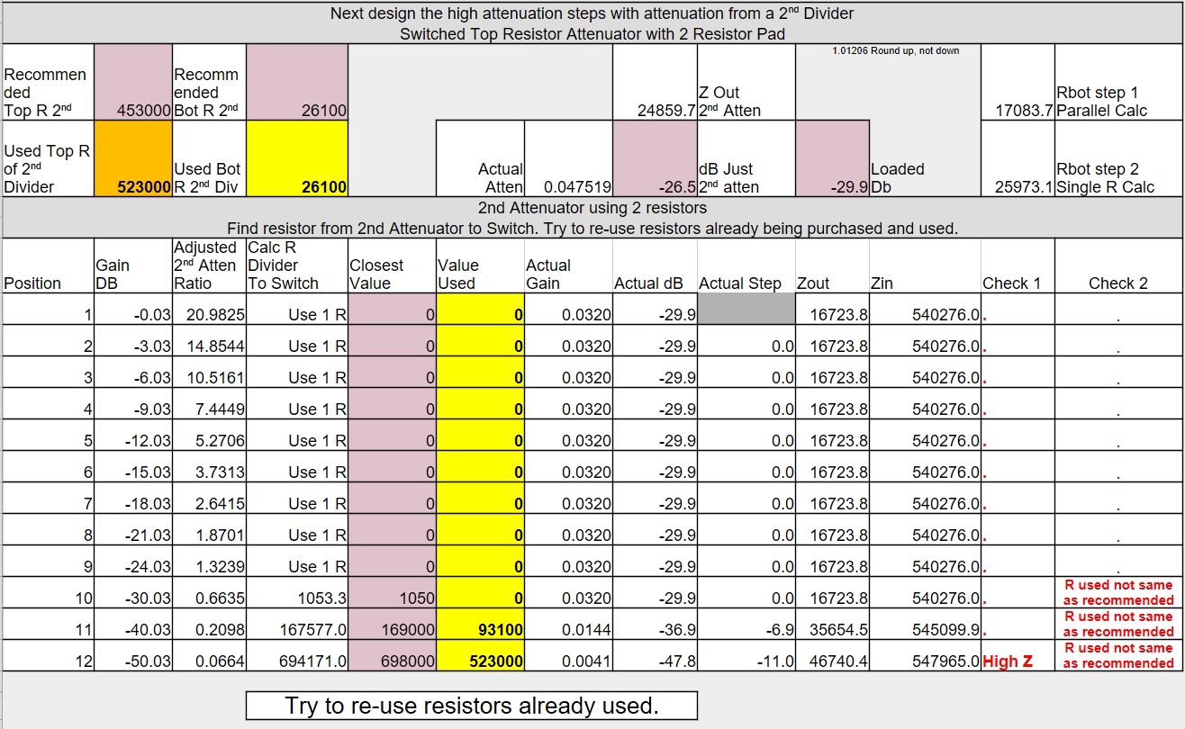
If you don’t like anything, save a copy of where you are at, and then change the values in the spreadsheet. The spreadsheet handles all the math for you.
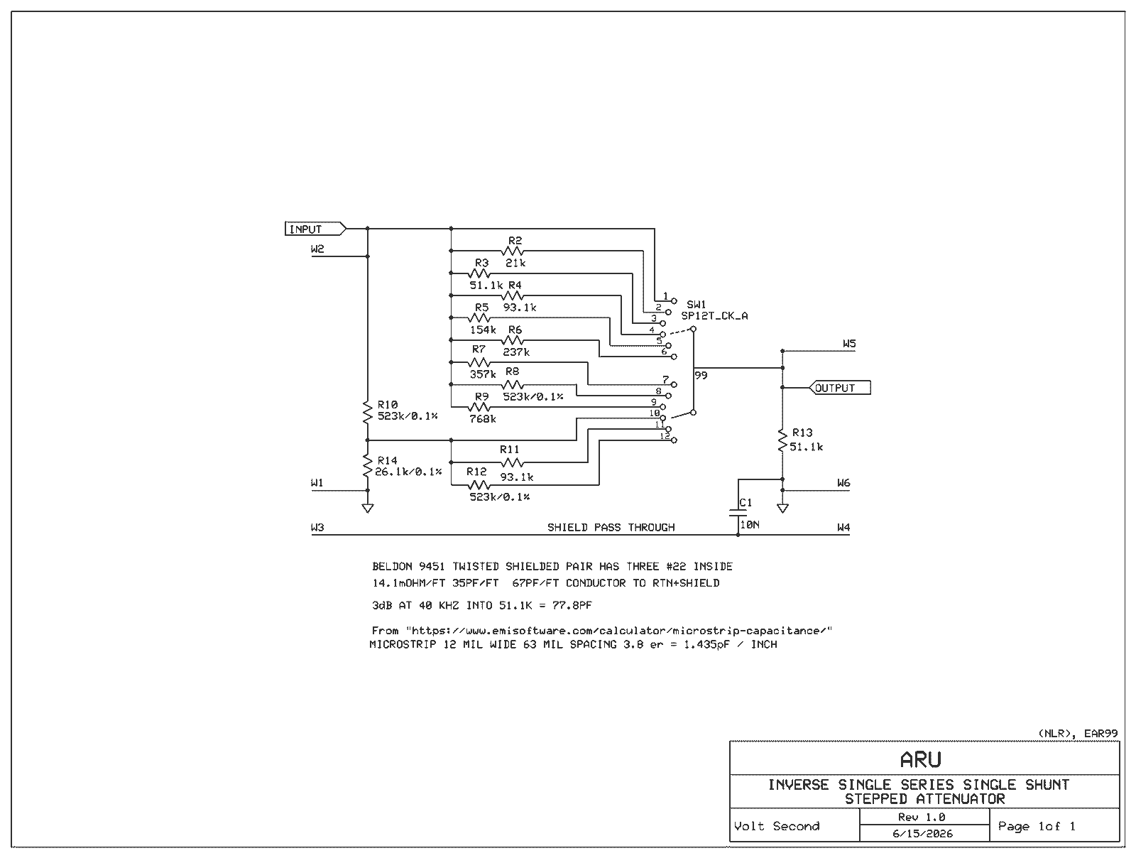
This design is made from the values we just calculated in the pages above.
I would pick a family of resistors that specified
< -30dB noise coefficient and
< 0.1 ppm voltage Coefficient and
<= 25 ppm/C temperature coefficient and
>180mW power rating
I normally shop at Digikey so having the parts both "active" and "normally stocked" is also important.
For the divider (R_Top and R_BOT) I'd splurge for a 0.1% resistor.
Vishay PLT 1206 meets all 4 goals at $3.81 in 1 pc quantity
Vishay PNM 1206 meets all 4 goals at $0.80 in 1 pc quantity
Vishay PTN 1206 meets all 4 goals at $0.61 in 1 pc quantity <- Looks like the best option
Vishay MCU/MCA 0805 and 1206 meet 2 goals at $0.60 in 1 pc quantity
Vishay D/CRCW e3 0805 and 1206 meet 1 goal at $0.11 in 1 pc quantity
Vishay PAT 1206 meets all 4 goals, but is not found at 51.1K in a Digikey search. I’ve seen the PAT series available in lower ohm choices.
The PLT, PNM and PTN did not have high ohmic values available in 0805 size parts, but supported up to 1meg in 1206. If you are laying out a board to hook the resistors up, use all 1206 sized parts.
0805 and 1206 size SMT resistors are fairly easy to solder, just use a water-soluble liquid flux, a small diameter eutectic solder, a pointy soldering iron at about 315C and gently clean the surface of the printed wiring board with a dry paper towel before soldering. Tin-Lead solder isn’t RoHS or Proposition 65 friendly, but it is easy to work with and doesn’t grow tin-whiskers. Just don’t hold it in your mouth between solder joints and wash your hands before you eat or use the bathroom.
When searching Digikey, I find it strange that in the late evening I can find PNM, PTN and PLT 51.1K resistors that are 1206 and the next day, I can only find one of them, and it is in a 0805 part.
Vishay CMF55 meets 2 and 1/2 conditions, but is a great part at $0.72 in 1 pc quantity <- Looks like the best option
Digikey lists this as 1/2 watt, Vishay lists it at 1/8W
Digikey offers this at 50ppm/C it is available in other sizes at 25ppm/C
This is also available as an RN55 military part, but I'd buy it as the CMF55
Vishay PTF states it has low noise and voltage coefficients, but it doesn't give values. $6.69 in 1pc quantities.
Vishay MBA/SMA meets 2 criteria, but does not list noise and voltage coefficient performance. $0.11 in 1 pc Quantities.
There are many options for the rotary switches. I'd pay $2 more and get the one with gold contacts.
E-Switch makes a $14.45 KC52A10.001NPF 12 position board mount switch with gold flash contacts.
C&K makes a $12.35 A11215RNCQ board mount switch with silver contacts
If you buy a switch with wire terminals instead of PC pins, you can build this attenuator with resistors that just hang off of the switch. You will want all bends in the resistor leads and solder joints to be greater than 1/8" inch from the body of the resistor (1/4 inch is perfect). This will keep from damaging the end caps on the resistors during handling.
While this design is intended to use a Break Before Make (BBM) switch, you can use it with a Make Before Break (MBB) shorting switch. With a Break Before Make switch, there is no "Pop" when changing volume levels. With the shorting switch, there will be a moderate increase in volume (about 4dB) as you change between switch positions. This isn't too bad of a "Pop,"


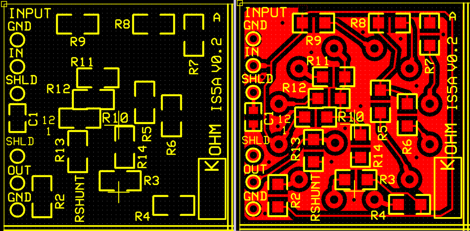
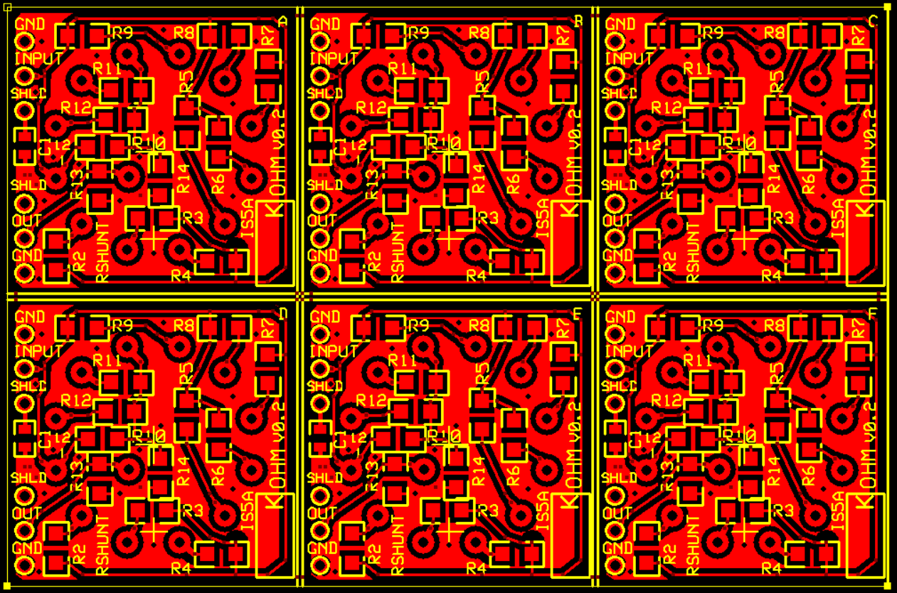
I decided to toss together an express PCB, 2 sided card for the attenuator. I flooded the unused areas with signal ground to help provide some shielding and sized the solder holes for #22 AWG stranded wire. If you are careful, you could fit #20 in these holes.
I chose to use 1206 resistors to keep the card small. I can fit 6X copies on a single protocard so an order gets me 18 card blanks after you cut them apart.
I cut my boards apart by
1. Covering the circuit traces with blue painter's tape
2. Holding a metal ruler on the score line and scoring a dozen times on top with a box cutter or an X-Acto knife. Then scoring the bottom a dozen times and repeating until the board "easily" snap apart. Don't use any more pressure than you would with a dull #2 pencil.
3. Score until it easily breaks apart. Don't force the snap, you can break the vias on the card if you bend the card too much.
4. Remove the Blue tape
5. Go outside and wipe the board off with 91% IPA.
I added a capacitor from shield to signal ground at the divider. There have been times when bypassing a ground signal to "shield/chassis" at the signal input has improved the noise performance. Yes, there have been times when it makes it worse, but that was in a circuit where my buddy didn't put a resistor between his op-amp's output to a long cable and the op-amp was oscillating because of C-Load issues. Start with the cap not installed and add it if needed. I've found 10nF to 0.22uF tends to work in this type of application. In several super noisy applications, an RC snubber between the shield and signal ground was the best. But I didn't have room to add the extra resistor without cutting up the ground plane. In one application, a 120 ohm resistor from shield to signal ground was the best. Most of the time if a cap is needed, a 10nF or 100nF does the trick, so that's what I designed with.
Over most of the layout, I ran the trace to trace spacing at 22 mils to keep the capacitance between traces small. There are a couple of exceptions like the "SHLD" to "GND" plane where I reduced the spacing for better routing. I tossed my first layout that had the traces slightly further apart for a layout with the shaft for the switch centered on the printed wiring board.
I've learned not to run thin traces directly to leaded solder joints, you need to put a 25 to 35 mil pad expand or a teardrop between the pad and the trace. The tin in the solder dissolves copper, and it is easy to make a thin trace "disappear." Time for Copper to dissolve in solder article.
The center of the volume knob is reasonably centered in the middle of the board.
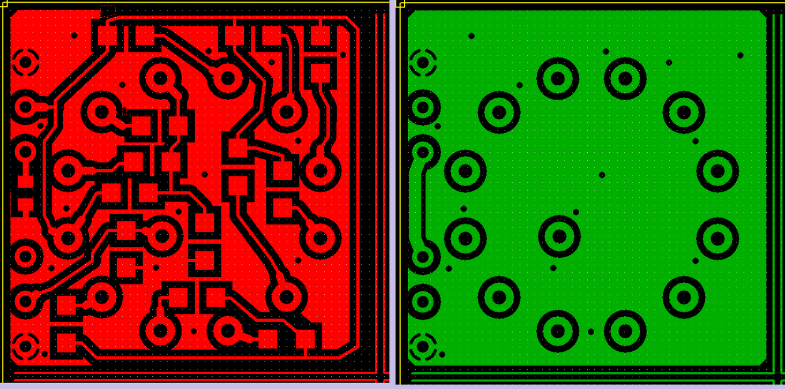
Below is the Silk Screen with and without the top layer copper. The REF-DES of the resistors corresponds to the pin number it goes to on the switch.
Both top and bottom layers at the same time. The parallel lines on the left and bottom are the cutting guides for the box cutter.
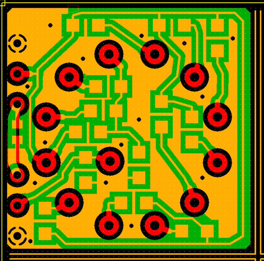
The routing top and bottom. The switch goes on the back side of the board. In the pictures, you are looking at the bottom of the rotary switch.
The terminal positions from the Littelfuse-CK-Rotary-A-Series-Datasheet:

After checking the routing in X-Check. You can duplicate the board 6 times before ordering the proto-board.
You can buy better parts, and you can buy less expensive parts, and you can buy cheaper parts. Several of the parts I pre-checked for availability can no longer be found at Digikey, so I searched for fairly good parts that were in stock. I believe the 25ppm/C does help with the sonic signature. The low ppm/C will partially make up for not listing low voltage coefficient. The parts that give a -30/-35dB noise coefficients in 1206 packages were no longer available.
|
Qty |
Name |
Order |
Part |
|
1 |
10N |
478-KAM21BR72A103KTCT-ND |
C1 |
|
1 |
154k |
YAG2012CT-ND |
R5 |
|
1 |
21k |
408-RG3216P-2102-B-T5CT-ND |
R2 |
|
1 |
237k |
P237KBCCT-ND |
R6 |
|
1 |
26.1k/0.1% |
408-RG3216P-2612-B-T5CT-ND |
R14 |
|
1 |
357k |
P357KBCCT-ND |
R7 |
|
2 |
51.1k |
541-TNPW120651K1BEEACT-ND |
R13,R3 |
|
3 |
523k/0.1% |
764-1305-1-ND |
R12,R10,R8 |
|
1 |
768k |
P768KBCCT-ND |
R9 |
|
2 |
93.1k |
13-RT1206BRD0793K1LCT-ND |
R11,R4 |
|
1 |
SP12T_CK_A |
KC52E01NPF-ND |
SW1 |
|
6 |
Hole_for_Wire |
None |
W1,W2,W3,W4,W5,W6 |
Yes, you can make it cheaper and use 1%
100ppm/C resistors, and you can use a cheaper switch. But how much is your
time worth? How much is your "bragging rights" worth? Spend a little more
and at least get the "slightly better" parts. Having a temperature
coefficient of less than 100ppm/C is a good start. Build it with the
moderately good parts first. If you like it, splurge for heavy gold plate
on silver contacts and for metal foil resistors.
First version 17-Jun-2026, Last update 17-Jun-2026.
Changes to correct font or spelling issues won't count as an update.
.
 ( New 2024 index page.)
 _(
Old 2003 index page.)
_(
Old 2003 index page.)
 _(
AMP Second index page.)
( Fancy index
page.)
_(
AMP Second index page.)
( Fancy index
page.)
.