(There are many more than six ways!)
(With Sweet Whispers Attenuator Advise too! )
Ver 1.7
The S5 Attenuation has been tried out by several people
who liked it enough to e-mail me about it.
I've made my own with HOLCOs and I like it. I'm saving
up to try some different resistor brands.
It has been long enough since I updated this page that I can stand to
look at it ;-).
I actually have started working on the formatting and grammar (quality)
as I find the time.
I'm keeping all the technical stuff with the updates. Hopefully the Newbies out there may learn a little from this. I am trying to simplify it more. But you do need to know how to run a Scientific Calculator to use this stuff. This site originated as a collection of emails I sent out to a few people answering questions on attenuators.
Please note: I won't calculate specific values for you if you email me. However, I have put an XLS spreadsheet to calculate resistor values on this site so you can do this yourself. I intend to add more instructions on how to use the spreadsheet soon. If you find an error, please email me and I will fix it.
If you post a question about the Sweet Whispers or shunt mode attenuation on the Bottlehead Forum, someone usually answers it. I may or may not choose to answer it. If I don't answer it, it is not because I don't like you, but because I'm increasingly short on time. I really want to build some of my advanced crazy ideas to see if they work. I've posted a few of the crazy ideas under the "sketches" section of my index page. A few people have built my untried ideas and wrote me that they worked well. That made my day! But I didn't get the hear them. . .bummer.
Shunt mode operation of attenuators is not my idea. I don't know who came
up with it. I'm just trying to explain the beast.
1.0 Basic Foreplay Attenuation Advise
Figure
1.0 Six Ways (of many) to Make an Attenuation
1.1 The recommended upgrade process is this:
1.2 An interesting note on Break In
1.3 A time saver if you need more attenuation
from the 0 to -30 dB Sweet Whispers or standard 100K pot:
1.4 A time saver
if you need more attenuation from the -20 to -50 dB Sweet Whispers:
1.5 The Easy Way to make the Stock Foreplay
Volume Control into a Shunt Mode Volume Control:
1.5.1 The Sweet Whispers Stepped Attenuator can be used in
Shunt Mode
1.6 The Secret Life of Pots link
1.7 Illustrated difference between standard
and shunt mode.
2.0 The beginnings of the S5 Attenuation.
Figure 2.0.1:
Stepped Attenuation Positions Viewed from Solder Side.
Figure 2.0.2:
Proper Way to Bend and Precut the Resistor.
Figure 2.0.3:
Loaded Attenuation
Figure 2.0.4:
Attenuator with ground wires installed in Chaperone Preamp.
2.1 Values for a 100K Series Input Impedance S5 Attenuation (-20
to -50 dB).
Table 2.1: 100 k
Series Single Shunt Stepped Attenuation (-20 to -50 dB)
2.2 Values for a 20.0K Series Resistor in a Single Series Single
Shunt Switched Attenuation (-1 to -40 dB).
Table 2.2: 20
K Series Single Shunt Stepped Attenuation (-1 to -40 dB)
2.2.1 200 k and 22.1 k Resistor Tricks:
Figure 2.2.1: Resistor
Tricks
to Replace the 20K Series Resistor.
2.2.1.1 The First Trick:
2.2.1.2 A Second Trick:
2.2.1.3 A Third Trick:
3.0 Trimming a volume pot's level with a
switched resistor.
Figure 3.0:
1.5
dB Trim for an Attenuation.
4.0 Spread Sheets For Calculating Attenuators
5.0 Math, Math and
Equations with Even More Math
5.1 Lets start with the equation for gain
expressed in dB:
5.2 When we express power in dB, the load
impedance must be constant.
5.3 Lets work the gain equation from 5.1
backwards and set K1 = V_out/ V_in:
5.3.1 The second equation is solving for
"V_out/ V_in = K1 . . . in terms of R_shunt.
5.3.2 Class, for homework . . . solve for
R_shunt for when you know R_series.
5.4 What is this 20 log
and 10 log stuff?
6.0 Adding Extra Attenuation to an Existing
Volume Pot.
6.1 One Resistor methods:
6.1.1 If you have a favorite resistor value
you want to use, R_add, the attenuation from adding series resistance is
given by:
6.1.2 If you know the dB attenuation you want:
6.2 Two Resistor (L-pad) Methods:
6.2.1 If you know the attenuation you want
from the output impedance of the L-pad (R_add) feeding your volume
control, use the following equations:
6.2.2 If you wanted 20 dB total attenuation,
6.2.3 Lets redo this with R_add = 75K and keep
20 dB total attenuation:
6.3 Lets do this
one more time and introduce a new formulae so We Can Pick the Series
Resistor in an L-pad.
7.0 Three Resistor Methods: (in work)
7.1 SHUNT MODE VOLUME CONTROL WITH A 20 dB
T-PAD ATTENUATOR
Figure 7.1: T-PAD
Go
here to get values for different attenuations.
7.2 You can use this T-PAD with a 10 k
pot/stepped attenuator
7.3 The ground on RT2 is important.
7.4 Installing a T-PAD in a Foreplay.
7.5 Deriving some of the T-PAD design
equations.
7.6 An example for a 20 dB T-PAD design with
100K output impedance.
8.0 Why does R_add (and the T-PAD) change the
dB per step in a shunt attenuator?
8.1 This is best explained by looking at a
T-PAD driving a volume pot in shunt mode.
8.2 Going back to the gain equation if R_out
is small compared to R_pot we can set it to zero and get:
8.3 What does this mean?
8.4 Lets look at three examples
9.0 The Padding of the output or the input of
a preamp both have benefits and deficiencies.
9.1 I find that padding the output results in
. . .
9.2 The first estimate of a design for the
Foreplay with split padding for a total of 20 dB extra attenuation
design is as follows. . .
9.3 Important NOTE:
9.4 If we want 20 dB attenuation in the
output instead of 10 dB:
10 What is this A-tube and B-tube stuff?
11 How do I use a VOM or DVM to find the
wiper and ground on an attenuator.
11.1 The simpler version to find the terminals with an Ohm
Meter.
11.2 The more complicated method to find the terminals
with an Ohm Meter.
12 Reducing the popping noise when changing
volume settings in Shunt Mode
In the Foreplay Preamp kit, changing a volume pot to a volume pot with shunt attenuation is easy and sounds better than the standard volume pot. Before you ask, the Sweet Whispers stepped attenuator used as a normal volume pot sounds considerably better than the stock volume pot with shunt attenuation. I personally think the Sweet Whispers in shunt mode (as in my Chaperone preamp) sounds better than in normal mode, but I'll bet a Dr. Pepper a few people will like it better in normal mode. That is the beauty of shunt mode conversion, it is easy to undo (just take out the wire cutters and snip.)
Sweet Whispers advice (10-Sep-00): When you build the Sweet Whispers, swap the resistor closest to ground (3xx ohms) with the next installed resistor (1xx ohms). This will make the first volume setting 7 dB lower. This reduction is great for back ground music late at night. The second volume setting will be the same as it was before.
Figure 1.0 Six Ways to Make an Attenuation
(There are many more than six ways!)
1.1 The recommended upgrade process is this:
1. Install the standard pot first to make sure things work. Listen for 1 week.1.2 An interesting note on Break In:
2. Convert to shunt mode by tying the wiper (center lug) to the right (top) pot lug and installing a 75K to 150K metal film series resistor between the top lug and the selector switch. Listen for 1 week.
3. Install the Sweet Whispers. Listen for 1 week.
4. Convert the Sweet Whispers to shunt mode using a 75k to 150k metal film. Listen for 1 week.
5. If the adjust range is good and you want more, upgrade the series metal film to a Caddock TF020, MK132, Vishay VSH, Holco, AN Tantalum or Resista.
6. If you are a good solderer and can read schematics, build a Single Series Single Shunt Stepped Attenuator (S5 Attenuator).If you can't listen for 1 week, play at least 10 CDs or LPs at each step.
It occasionally can take a couple days for the changes to break in. Don't worry if the change sounds odd at first. I can't explain this effect, but it happens.
If you have made the 0 to -30 dB Sweet Whispers and wish you had made the -20 to -50 dB version instead, relax there is an easy fix for this.1.4 A time saver if you need more attenuation from the -20 to -50 dB Sweet Whispers:First, take the 90.9k resistor included in the Sweet Whispers kit for the -20 to -50 dB version and install it:
Lift the wire going to the selector switch from the right terminal of the Sweet Whispers. Lift (unsolder) this wire at the Sweet Whispers end of the wire.Now go buy a 11K (10k to 12k is just fine) metal film (or other high grade resistor) and place it across the Sweet Whispers. Solder this resistor from the ground connection (left terminal) to the top input connection (right terminal) of the Sweet Whispers. This puts this resistor in shunt with the Sweet Whispers.Place this resistor between the wire you lifted and where the wire used to go. This puts the resistor in series with the selector switch.
This give us a 20.1 to 50.1 dB attenuator!
19.3 dB of this attenuation comes from the "L-pad" made from the 90.9K and 11K resistors.
0.8 dB comes from the 9.81K output impedance of the "L-pad" feeding the Sweet Whispers.(Much more on "L-pad" below.)
The bad news: This quick fix will not work if the Sweet Whispers is used in shunt mode. You need to make a T-PAD attenuator if you want to use the 100K Sweet Whispers in shunt mode. There is information below (even a picture) on how to design this T-PAD attenuator.
Again, this quick fix will not work if the Sweet Whispers is used in shunt mode. You need to make a T-PAD attenuator if you want to use the -20 to -50 dB Sweet Whispers in shunt mode with additional attenuation. There is information below (even a picture) on how to design this T-PAD attenuator.To get more attenuation from the -20 to -50 dB Sweet Whispers, just place a "shunt" metal film resistor from the left (ground) Sweet Whispers terminal to the right (top) Sweet Whispers terminal.
What value shunt resistor:
--> A 5.1K resistor give you a total of 28.9 dB minimum attenuation. <--
This is three "clicks" more attenuation than you had before. You now have a 29 to 59 dB Sweet Whispers.Three clicks is 8.9 dB more than the stock 20 to 50 dB attenuation.25.5 dB of this attenuation comes from from the 90.9K and 5.1K "L-pad" we just made.
3.4 dB comes from the 4.83 K output impedance of the L-pad feeding the stock stepped attenuator.--> A 2.2K resistor gives you a total of 34.2 dB minimum attenuation <--
This is 4 3/4 "clicks" more attenuation than you had before. You now have a 34 to 64 dB Sweet Whispers.32.5 dB comes from the 90.9K and 2.2K L-pad.
1.7 dB comes from the 2.15 K output impedance of the L-pad feeding the existing 10K attenuator.
1. Remove the wire connection from the top (right terminal) of the volume pot to the selector switch at the volume pot end.2. Insert a resistor between the volume pot top (right terminal) and the loose wire going to the selector switch.
This resistor is typically 47.0K (3.3 dB minimum attenuation) to 200K (9.5 dB minimum attenuation) metal film when using a 100K volume pot.3. Run a short wire from the wiper (middle terminal) to the top (right terminal) of the volume pot.Using this method (Shunt Mode Easy Way) will reduce the any noise you get when you adjust the volume when compared to (Shunt Mode Pot Typical). I have been told it sounds better this way too. I didn't notice too much of a change with the stock Foreplay pots, but I didn't have a hot rodded Paramour to drive my speakers at that time either.
1.5.1 The Sweet Whispers Stepped Attenuation can be used in Shunt Mode
The Sweet Whispers stepped attenuator can even be used in shunt mode the same way a pot is used in shunt mode. I think it sounds good this way and I have received a couple e-mails that say it sounds great this way.
If you are using a -20 to -50 dB Sweet Whispers, skip to step 3 given in Section 1.5 and you are done.
If you are using a 0 to -30 dB Sweet Whispers, follow the all steps listed in Section 1.5.
I was sent this link by an e-mail buddy. It does a good job at explaining
some of the issues with attenuators. (9-Dec-00)
The
Secret
Life of Pots
This may help you visualize the difference between the different attenuators. (1-25-02)
This is a standard stepped attenuator. All the resistors are soldered in
series and the wiper picks the solder joint you listen to.
Note: If the wiper goes open, you get no volume.
This is a stepped attenuator that has been converted to shunt mode. The
pot is in the shunt position. You now only listen to the resistor and
solder joints between the wiper and ground and to the one resistor going
to the selector switch.
Note: If the wiper goes open, you get minimum attenuation.

This is a Single Series Single Shunt Stepped Attenuation (S5 Attenuation
for those of you who must abbreviate.) With this attenuator only two
resistors are in the signal path at one time.
Note: If the wiper goes open, you get everything the preamp has to give
for there is not attenuation in the volume control at all with this
fault..
Since we can make a Sweet Whispers into a shunt mode attenuator and have it sound better, I was thinking, why not make a version of the Sweet Whispers with individual shunt resistors. This would eliminate almost a dozen solder joints and resistors in the signal path at every volume setting.
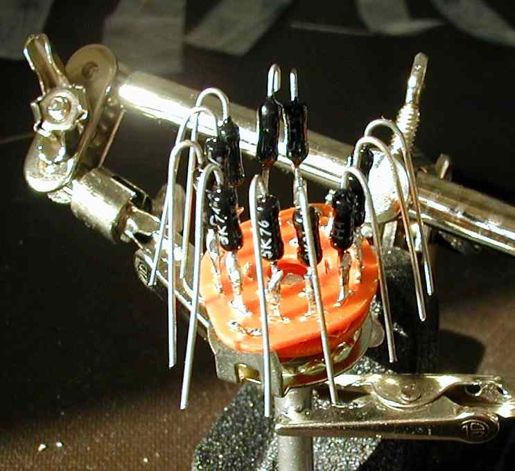
The 12 position switch would be wired like this:
1. The wiper connects to the selector switch through a 100K resistor and the wiper is also connected to the grid of the tube just like normal.Figure 2.0.1: Stepped Attenuation Positions Viewed from Solder Side.
2. Positions 1-11 connect to only one resistor. The other ends of all 11 resistors are tied together and go to ground.
3. Position 12 ties directly to ground.
Figure 2.0.2: Proper Way to Bend and Precut the Resistor.
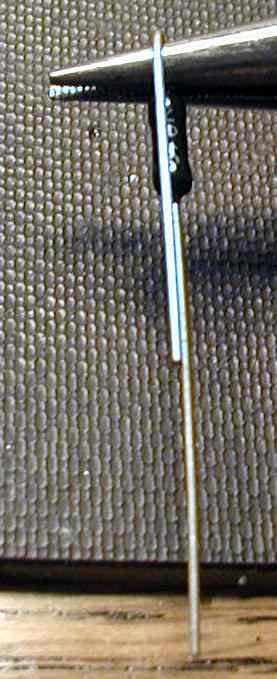
I like to bend the lead towards the marking so that when it is installed,
I can read the value. Some people believe all the values should read the
same direction, either all up or all down, for best sound. I try to
arrange them all the same way because it looks better that way. I want it
to look like I was paying attention to what I was doing.
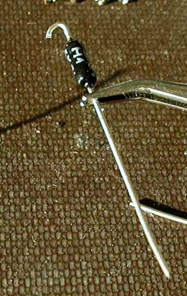
Figure 2.0.3: Loaded Attenuation
When bending the leads, don't forget to hold the lead to body connection of the resistor steady with a needle nose to make sure you don't crack or stress the end cap of the resistor. Be careful, some high end resistors have delicate construction. You don't expect a sports car to haul 2 tons of gravel from the quarry and still work like a sports car.
Figure 2.0.4: Attenuation with ground wires installed in Chaperone
Preamp.
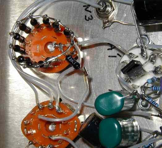
* Note how I left a large hole in the back of the attenuator with the
ground wire. This is so you can get down to the wiper with the soldering
iron.
* Also note that the ground wire does make a circle. I have a gut feeling
that this will provide a little shielding and I know it makes the
attenuator stronger.
* The brown discoloration on the Teflon (tm) sleeving is flux that wicked
up the sleeving that I can't get off with flux remover.
I optimized the resistors listed in the table below for a 100 k resistor to the selector switch, for a -20 to -50 dB attenuation and for easily obtainable high quality resistors. If we use a different value resistor between the stepped attenuator and the selector switch, we'll still get reasonable attenuation and step sizes for series resistor values as low as 10 k.
Please note that there is nothing magic about having exactly 15.00000 dB or 20.00000 db minimum attenuation. It looks cool, but that is about it.
There is very little magic in using a 100 k between the wiper and the selector switch. However, it is nice to have the even step sizes that come with the 100 k series resistor. If we use a 11.0 k to the selector switch instead of a 100 k with the values listed in the table below, the step sizes start at 1.7 dB and end at 3 dB per step. That is livable, but it could be better. With resistors 100 k and above, a nice 3 dB per step is achieved.
Note: Michael Percy's Caddock MK132 is $0.55 less expensive if you buy a 95.3 k resistor value than if you buy a 100k resistor value. If I were buying a MK132 100k for this attenuator, I'd buy the 95.3k and save a $1.10 for the pair of attenuators. The dB per step with a 95.3 k resistor will be just fine.
Table 2.1: 100 k Series Single Shunt Stepped Attenuation (-20 to -50 dB)
| Series Resistor Value to Selector Switch: | 100K | Step Size | 11.0K | Step Size | 47.0K | 200K | 487K | |||||
| Position | Closest Michael Percy Catalog Value | dB | dB | dB | dB | dB | dB | dB | ||||
| 1 | 11.0K | -20.1 | 2.86 | -6.0 | 1.70 | -14.4 | -25.7 | -33.1 | ||||
| 2 | 7.68K | -22.9 | 3.14 | -7.7 | 2.12 | -17.0 | -28.6 | -36.2 | ||||
| 3 | 5.23K | -26.1 | 2.99 | -9.8 | 2.23 | -20.0 | -31.9 | -39.5 | ||||
| 4 | 3.65K | -29.1 | 3.02 | -12.1 | 2.44 | -22.8 | -34.9 | -42.6 | ||||
| 5 | 2.55K | -32.1 | 2.87 | -14.5 | 2.45 | -25.8 | -38.0 | -45.7 | ||||
| 6 | 1.82K | -35.0 | 3.08 | -17.0 | 2.74 | -28.6 | -40.9 | -48.6 | ||||
| 7 | 1.27K | -38.0 | 2.87 | -19.7 | 2.65 | -31.6 | -44.0 | -51.7 | ||||
| 8 | 909 | -40.9 | 2.90 | -22.3 | 2.73 | -34.4 | -46.9 | -54.6 | ||||
| 9 | 649 | -43.8 | 3.11 | -25.1 | 2.98 | -37.3 | -49.8 | -57.5 | ||||
| 10 | 453 | -46.9 | 3.12 | -28.1 | 3.02 | -40.4 | -52.9 | -60.6 | ||||
| 11 | 316 | -50.0 | N/A | -31.1 | N/A | -43.5 | -56.0 | -63.8 | ||||
| 12 | 0 | MUTE | MUTE | MUTE | MUTE | MUTE |
If I stray from the Michael Percy Holco list, the step sizes can be made closer to 3.0 dB per step. I'm not sure if that is worth anything. I just wanted to mention it.
If you are using an L-pad attenuator that never goes to 0 dB attenuation
(like the one above), consider using the Single Series Single Shunt
Stepped Attenuation. The -20 dB to -50 dB attenuator only changes from 100
k to 111 k from full volume to full mute.
With this set of values, I chose resistors that would give closer to 3.0 dB step sizes instead of trying to have the attenuation be an exact multiple of 3.000000. The first step has a resistor attached to it to make sure there is always a DC path to ground even with the input source disconnected.
I picked 20K because I believe that values below 20K would make the source (CD player, tuner, turntable amplifier etc.) start to work a bit hard. 20K has the advantage over 100K because is should be a bit quieter and should be a little less susceptible to noise pick up. (This is getting to be an awfully complicated decision for just a volume control!) I have values above 100K in the Sweet Whispers in both my Foreplay and Chaperone preamps because I thought it was more important to make the load easy on the source than it was to suffer a little more noise pick up. When I made my S5 attenuator, I chose the 20K values.
A 22.1K in parallel with a 200K gives us a 20K resistor. The 22.1K column was an attempt to see what would happen if we left the 200K resistor out. This 200K can be used for several interesting tricks I will discuss later.
Buy the cheap metal film resistors first, if you like what you hear keep them. If it is close and you want more, buy the better resistors or tweak the values. Have fun, smell the rosin, enjoy the music. . . but don't worry what I or anybody else thinks, after all it's your equipment.
Table 2.2: 20 K Series Single Shunt Stepped Attenuation (-1 to
-40 dB)
(Note: These 20K values are the values I used in my attenuator.)
| Resistor Value to Selector: | 20.0k | Step Size | 22.1k | Delta to 20.0k | 47.0k | Step Size | 200k | 487k | Step Size | |||||
| Position | Closest Michael Percy Catalog Value | dB | dB | dB | dB | dB | dB | dB | dB | dB for 487k | ||||
| 1 | 165.K | - 1.0 | 3.02 | - 1.1 | -0.1 | - 2.2 | 5.3 | - 6.9 | -11.9 | 11.8 | ||||
| 2 | 34.0K | - 4.0 | 2.97 | - 4.3 | -0.3 | - 7.5 | 4.3 | -16.8 | -23.7 | 6.1 | ||||
| 3 | 16.2K | - 7.0 | 2.98 | - 7.5 | -0.5 | -11.8 | 3.8 | -22.5 | -29.8 | 4.7 | ||||
| 4 | 9310 | -10.0 | 3.05 | -10.6 | -0.6 | -15.6 | 3.6 | -27.0 | -34.5 | 4.1 | ||||
| 5 | 5760 | -13.0 | 3.04 | -13.7 | -0.7 | -19.2 | 3.4 | -31.1 | -38.6 | 3.7 | ||||
| 6 | 3740 | -16.1 | 2.88 | -16.8 | -0.7 | -22.6 | 3.2 | -34.7 | -42.4 | 3.3 | ||||
| 7 | 2550 | -18.9 | 3.00 | -19.7 | -0.8 | -25.8 | 3.1 | -38.0 | -45.7 | 3.3 | ||||
| 8 | 1740 | -21.9 | 2.94 | -22.7 | -0.8 | -28.9 | 3.1 | -41.3 | -49.0 | 3.1 | ||||
| 9 | 1210 | -24.9 | 6.18 | -25.7 | -0.8 | -32.0 | 6.3 | -44.4 | -52.1 | 6.4 | ||||
| 10 | 576 | -31.1 | 9.03 | -31.9 | -0.8 | -38.3 | 9.2 | -50.8 | -58.6 | 9.2 | ||||
| 11 | 200 | -40.1 | N/A | -40.9 | -0.9 | -47.5 | N/A | -60.0 | -67.7 | N/A | ||||
| 12 | 0 | MUTE | MUTE | MUTE | MUTE | MUTE |
Notes:
1. Something like the stepped attenuator above, but quite a bit fancier,
appeared in Audio Amateur years ago.
2. Position 10 is purposely a 6 dB step with a 20 k input.
3. Position 11 is purposely a 9 dB step with a 20 k input.
2.2.1 200 k and 22.1 k Resistor Tricks:
Figure 2.2.1: Resistor Tricks to Replace the 20K Series Resistor.

2.2.1.1 The First Trick:
What is nice about the Table 2.2 arrangement is that if we feed the stepped resistor shunt (the wiper of the 12 position switch) with an L-Pad made from a 22.1K to ground and a 200 k resistor to the input we get a 20K output impedance from the L-Pad (to keep the step sizes the same) and an extra 20 dB attenuation.
So now we have a 21 dB to 60 dB attenuator.
2.2.1.2 A Second Trick:
Attach the 22.1 k between the input selector and the stepped resistor shunt.This gives us a -0.91 dB trim for every value shunt resistor listed above and a 19.9 k output impedance.
Attach one end of the 200 k to the stepped resistor shunt
Attach the other end of the 200 k to the center of a SPDT switch. One end of the switch goes to the input selector, the other end goes to ground.
With different values for the 22.1 k and 200 k, we can have a 20 k output
impedance and a -1.5 dB trim (half of 3.0 dB.)
Another decent pair of HOLCO values would be 24.3 k and 130 k for a -1.49
dB step and a 20.5 k output impedance.
A different pair would be 22.1 k and 118 k for a -1.49 dB step and 18.6 k
output impedance.
2.2.1.3 A Third Trick:
Attach the 200 k between the input selector and the stepped resistor shunt.In one switch position we have a -1 to -40 dB attenuator.
Attach one end of the 22.1 k to the stepped resistor shunt
Attach the other end of the 22.1 k to the center of a SPDT switch. One end of the switch goes to the input selector, the other end goes to ground
To get a trimmer for the shunt regulator that has a constant dB adjustment, we have to get a bit fancier and make an input divider with a constant output resistance. The constant output resistance makes the dB change from throwing the switch independent of the volume pots resistance. 24.3 k and 130k are not magic values, I picked them because in parallel they equal 20.5k. For resistors in parallel:
1/R_equivalent = 1/R1 + 1/R2 . . . 1/R_last_one_in_parallel.
Link to a different
trimming method for a volume control.
The two attenuators on the left have the trim switch set to ground and provide an extra 1.5 dB attenuation. The two attenuators on the right have the trim switch set to the input and this removes the attenuation. If the input source has zero impedance (or at least small compared to 20.5k), the input can be considered an AC short. Because both the 24.3k and 130k have AC shorts on one side of them, the two resistors always present the same output impedance to the 9310 and 34.0k shunt resistors. This constant output impedance keeps the dB per step the same regardless of the position of the trim switch.
Figure 3.0: 1.5 dB Trim for an Attenuation.
This two resistor trim method shown in Figure 3.0 does
not keep the input impedance to the attenuator constant. For small
changes in input impedance, the source won't care about the change in
input impedance..
The following is an EXCEL 97 spreadsheet I am working on to calculate attenuator values. The individual pages are locked, but are not password protected. When I uploaded it on 15-Jul-01, Norton AV. said it was clean. Please check it with your own anti virus software before you use it. It is possible it has picked up a virus somewhere besides from me.
In this spreadsheet, I have a sheet for normal attenuators, shunt mode attenuators, S5 attenuators and a sheet for L-pad and T-PAD attenuators. The spreadsheet calculates the exact resistor value and then pick the closest 1% resistor and the closest Michael Percy Holco resistor.
I am only posting the zipped version of the file. The unzipped version occupies almost 500K of precious ISP space. If you don't own Microsoft Excel you can still view the spreadsheet. Some viewers will let you change values, some others will not. If you download one that won't let you change values, try an older version of the viewer. Click here for a Link to Microsoft viewers (Link Broken). <- Old --> newer Excel Viewers (2022) Or try to run it in OpenOffice Calc (it should work) Open Office (free) Calc (An Excel equivalent) .
I'll derive the equations I am using below to help you feel comfortable with the equations I am using.
5.1 Lets start with the equation for gain expressed in dB:
dB = 20 dB * log( V_out/ V_in)"Log" is short hand for log base "10" versus "ln" with is log base "e".
Negative gain is also known as attenuation. Negative gain is expressed as positive attenuation.
A gain of -11 dB equals an attenuation of +11 dB.5.2 When we express power in dB, the load impedance must be constant. The equation for differences gain in dB when we know the power into a fixed load impedance is:
dB = 10 dB * log( P_out/ P_in)
5.3 Lets work the gain equation from 5.1 backwards and set K1 = V_out/ V_in:
dB gain = 20 dB * log( K1 ) The starting point.5.3.1 The second equation is solving for "V_out/ V_in = K1 = R_shunt/ ( R_shunt + R_series)" in terms of R_shunt.
dB gain/20 dB = log (K1) divide both sides by 20 dB
10^( dB gain/20 dB) = K1 take the antilog of both sides.
K1 = 10^( dB gain/20 dB) swap sides of the equation for neatness
K1 = R_shunt/ ( R_shunt + R_series) The starting point.Now if we know the dB attenuation we want, we can solve for K1.
K1 * (R_shunt + R_series) = R_shunt Multiply both sides by
(R_shunt + R_series)
K1 * R_shunt + K1 * R_series = R_shunt Expand left side of equation
K1 * R_series = R_shunt - K1 * R_shunt Subtract K1 * R_shunt from both sides
K1 * R_series = R_shunt *( 1 - K1) collect terms on right
R_series = R_shunt * (1 - K1)/ K1 divide both sides by K1
5.3.2 Class, for homework you can go through a similar exercise and solve for R_shunt for when you know R_series. ;-)
R_shunt = R_series * K1/(1 - K1)
When you calculate gain using voltage or current the equation to use is:
Gain in dB = 20 dB * log( V_out/ V_in)Remember if the gain in dB is negative, you actually have attenuation. Gain and attenuation are usually expressed as a positive numbers. But if you see a sign change in either. You should now know what to do.
Gain in dB = 20 dB * log( I_out/ I_in)
When you calculate gain using powers the equation to use is:
Gain in dB = 10 dB * log( P_out/ P_in)The power has to be in the same units. If P_out is in milliwatts, P_in has to be in milliwatts. If P_out is in watts, P_in has to be in watts. There are ways to use different value units, but that is risky unless you are good at doing math in your head. To be valid when you express power in dB, you also have to express the impedance the power is referenced to. It is not fair (when is marketing fair?) to compare 1W into 8 ohm to 1W into 4 ohms.
Why is it "10" log instead of "20" log?
The factor of 10 instead of 20 comes in because of a rule of logarithms that says:
y * log( x) = log( x **y)
Power = V^2/ R.Putting V^2/ R into the gain equation for power gives:
Power = I^2 * R
Gain in dB = 10 dB * log( (V_out^2/ R) / (V_in^2/ R) )Gain in dB = 10 dB * log ( V_out^2/ V_in^2) Cancel out the "R" on top and bottom
Gain in dB = 10 dB * log ((V_out/ V_in )^2 ) Collect terms
Gain in dB = 10 dB * 2 * log( V_out/ V_in ) Log of a number raised to a power
equals the power times the log of
the number.
Gain in dB = 20 dB * log( V_out/ V_in) Look familiar?
6.1.1 If you have a favorite resistor value you want to use, R_add, the attenuation from adding series resistance is given by:
20 * log (R_pot /(R_add + R_pot)If the attenuation is good enough with just one resistor for R_add, you are done. Go buy R_add and solder it in.
If R_pot = 100k and R_add = 90.1k: 20 * log (100k /(100k + 90.1k)) = -5.58 dB.
If R_pot = 34 k and R_add = 24.3k: 20 * log (34k /(34k + 24.3k)) = -4.68 dB.
If R_add is very large you should use the two or three resistor method. Some people think 51k is too big, other think 500k is too big. Looking at the Figure 3.0 above, if your volume pot were a 34K volume pot (R8) and a 24.3k (R9) series resistor gave both enough attenuation and was a reasonable part value, you don't need to install R7 to make an "L-pad".
I think having R9 = 200K is as big as we want to go.
Is 300K evil (too high of a value)?. . . No, it is not.
Is 200K always a low enough value not to cause problems?. . . No, it is
not.
200K is just a line in the dust.
6.1.2 If you know the dB attenuation you want:
k1 = 10^( -dB/20 dB) (Note: k is the voltage ratio equivalent to the desired dB attenuation.)1022k is way to big in my un-humble opinion. 301k is pushing my comfort level. However, may people think 1.022 meg (1022k) is just fine.
R_add = R_pot (1 - k1)/ k1If R_pot = 100k and you want 12 dB,
k1 = 0.251,
R_add = 100k * (1-.251) /.251 = 298 k (294k and 301k are available)If R_pot = 100k and you want 21 dB,
k1 = 10^(-21/20) = 10^-1.05 = 0.0891,
R_add = 100k * (1-.0891)/.0891 = 1022k
Note: 12 dB = 4 steps on a Sweet Whispers used in normal attenuator mode (21 dB = 7 steps.)
6.2 Two Resistor (L-pad) Methods:
With two resistors, you can control either the input impedance or the output impedance, but not both. There will be two attenuations to pick.
The first attenuation is from adding series resistance. This is picked similar to the one resistor attenuation method in 6.1: either pick a favorite resistor value or assign an attenuation.6.2.1 In this case, R_add is the effective impedance of the two added resistors in parallel. If you know the attenuation you want from the output impedance of the L-pad (R_add) feeding your volume control, use the following equations:This series resistance, R_add, is actually the parallel combination of the two resistors we are adding, R_series and R_shunt.
The second attenuation is from of the input divider (the L-pad) itself.
The total attenuation of these two attenuations equals the sum of the two attenuators in dB.
k1 = 10^( -dB/20 dB) (Note: k is the voltage ratio equivalent to the desired dB attenuation.)6.2.2 If you wanted 20 dB total attenuation, lets assign 8 dB to the attenuation from R_add (the output impedance of the attenuator) and the remaining 12 dB to the divide ratio made using two resistors for R_add. These equations calculate the two resistors values:
R_add = R_pot * (1 - k1)/ k1Example if you want 8 dB attenuation from R_add with R_pot = 100K:
k1 = 10^(-8 dB/20 dB) = 0.398
R_add = 100k * (1 - 0.398)/0.398 = 151.26 k . . . use 150 k
Check the work: 20 * log [100 k / (100k + 150k) ] = -7.96 dB . . . close enough.
k2 = 10^( -dB/20 dB)If we were looking at Figure 3.0 above, "R series" is equivalent to R9, "R shunt" is equivalent to R7, R_pot is equivalent to R8. If you don't like the two resistor values, pick a different starting attenuation. Again, 590k seems very large to me.
R_add = 1/( 1/ R_shunt + 1/ R_series )
(Remember: R_add is an effective resistance,
not a physical resistor you can hold in your hand.)
R_shunt = R_add * (1 + [ k2 / (1 - k2 ) ] )
R_series = R_shunt * (1 - k2)/ k2Example continued with 12 dB attenuation and R_add = 151.26 k:
k2 = 10^(-12 db/20 dB) = 0.251
R_shunt = 151.26k * [1 + 0.251/(1 - 0.251)] = 151.26k * 1.335 = 201.9k use 200k
R_series = 200k * (1 - 0.251)/0.251 = 200k * 2.98 = 596.8k use 590k
Check for attenuation: 20 * log( 200k/( 590k + 200k) ) = -11.9 dB close enough
Check for R_add: 1/(1/200k + 1/590k) = 149.4k close enough
6.2.3 Lets redo this with R_add = 75K and keep 20 dB total attenuation:
dB from R_add = 20 * log (R_pot /(R_add + R_pot)We still have a resistor greater than 200k for R_series. (200K is my semi-arbitrary pain threshold.) Also notice that we halved R_add, but the values we used did not halve.If R_pot = 100k and R_add = 75k:
= 20 * log (100k /(100k + 75k)) = -4.86 dB.20 dB total - 4.86 dB = 15.14 dB from the divide ratio.
k2 = 10^(-15.14 db/20 dB) = 0.175
R_shunt = 75.0k * [1 + 0.175/(1 - 0.175)] = 90.9k use 90.9k
R_series = 90.9k * (1 - 0.175)/0.175 = 428k use 422k
Check R_add = 1/(1/90.9k + 1/422k) = 74.79k (close enough)
Check attenuation = 20 * log ( 90.9k/( 90.9k+ 422k))= 15.03 dB (close enough)
Total attenuation is 15.03 dB + 4.86 dB = 19.99
6.3 Lets do this one more time and introduce a new formulae so We Can Pick the Series Resistor in an L-pad.
I am going to force R_series to be 90.9k, assume we still have a 100k pot and calculate R_shunt:
k3 = 10^( -dB/20 dB)However, our R_add output impedance is now:
R_bottom = R_series * k3 /( 1-k3)
R_shunt = 1/( 1/R_bottom - 1/R_pot)k3 = 10^(-20 dB/20 dB) = 0.100
R_bottom = 90.9k * 0.1/(1-0.1) = 10.1k
R_shunt = 1/(1/10.1k - 1/100k) = 11.2k, use 11.0k in parallel with the 100k Pot.
R_add = 1/(1/11.0k + 1/ 90.9k) = 9.81k!This low of an output impedance (9.81 k) driving a 100k pot means that if we use the pot/stepped attenuator in shunt mode, our dB per step will be seriously reduced. (Darn, Darn, Darn, why does that "There ain't no such thing as a free lunch, TANSTAAFL" thing keeps showing up.)
Check gain from L-pad = 20 * log[ 11 k/(11 k + 90.9 k) ] = -19.3 dB
Check gain from R_add feeding 100K pot = 20 * log[ 100 k/(100 k + 9.81 k)] = -0.81 dB
Total gain = -19.3 dB - 0.81 dB = -20.1 dB gain at maximum volume
Total attenuation = +19.3 dB + 0.81 dB = +20.1 dB attenuation at maximum volume
Remember, negative gain is positive attenuation.
We are trying to control three things with only two choices. To control three things, we'll need three resistors or a "T" attenuator.
However, if you do not want to use shunt mode, buy your two resistor values, install them and enjoy the music. I have tried a two resistor attenuator with the stock 100k pot, both the stock pot in shunt mode and the Sweet Whispers in normal mode sound much better to me than having the stock pot in the circuit.
Figure 7.1: T-PAD
82k is just as good as 82.5K.
The first 14.2 dB comes from RT2 and RT1.
The second 6 dB comes from the 100k (98.6k) output impedance of the T
pad and the 100K volume pot.
14 dB + 6 dB = 20 dB
RT1, RT2 and RT3 make up the "T" attenuator. It is called a "T" attenuator or "T-PAD" because it looks like a "T" when you draw it. The T-PAD is used when you want independent control of the input impedance, the attenuation and the output impedance. To control three things you need three variables, thus the three resistors. The T-PAD is also used when you want to avoid high value resistors. High value resistors have issues with noise pickup and drift.
Go here to get values for
different attenuations. (I haven't typed up the formulas to
calculate this yet.)
Once you get there click on "T and H pads" in the upper right corner.
In "Input impedance of attenuator" type 100000
In "Output impedance of attenuator" type 100000
In "Attenuation required in decibels (1-40):" type 20
Then click on "Calculate resistor values" and scroll down the page to see
the part values.
Round the value to the nearest part value you can buy.
This T-PAD attenuator technique also work well into a normal volume pot or stepped attenuator.
Shunt mode is highly recommend if you use this T-PAD. The high output impedance will keep the step size close to the original step sizes.
If you use 100K for both RT1 and RT3 while feeding a 100 k pot (or 100 k Sweet Whispers), the total attenuation is 22.3 dB.
15.6 dB of the attenuation comes from the RT1 and RT2.With RT1 and RT3 equal to 82k, 90.9k or 100k, this arrangement is a good choice if you want to use the 100 k Sweet Whispers in shunt mode. The difference between 22.3 dB and 20.0 dB is not worth worrying about.
6.7 dB of the attenuation comes from the 116.6k output impedance feeding the 100 k pot.
30 dB attenuation note:
If you want 30 dB instead of 20 dB, change RT2 from 20 k to 6.8 k (6.2 k is OK.)7.2 You can use this T-PAD with a 10 k pot/stepped attenuator
With the 100 k Sweet Whispers and RT1/ RT3 = 100 k, RT2 = 6.8 k gives 30.2 dB attenuation.
With RT1/ RT3 = 82 k, and RT2 = 6.8 k, gives 27.8 dB attenuation.
With RT1/ RT3 = 100 k and RT2 = 6.2 k gives 30.9 dB attenuation.
If you use the above T-PAD with the 10 k Sweet Whispers, the 14.2 dB from RT2 and RT1 stays the same, but the 98.6 k output impedance adds 20.7 dB attenuation instead of 6 dB attenuation. 14.2 dB + 20.7 dB = 34.9 dB or 35 dB between friends.
Replacing the resistor from the selector switch to the attenuator with the T-PAD above will turn the -20 to -50 dB Sweet Whispers into a -35 to -65 dB Sweet Whispers. If you are currently listening on the bottom volume setting, this volume setting will now be about 5 clicks higher on the -20 to -50 dB Sweet Whispers attenuator.
7.3 The ground on RT2 is important.
Any noise on RT2's ground wire will be directly injecting into your input signal. You may want to give it it's own wire to your single point ground.
7.4 Installing a T-PAD in a Foreplay.
This is one way of many to install the T-PAD. It is not what I call optimum, but it is good enough in most cases. This method is also easy to undo if you don't like it.
1. Remove the wire connection from the top (right terminal) of the volume pot to the selector switch at the volume pot end.
2. Insert RT3 into the top of the volume pot (right terminal) and solder.
3. Attach RT2 from the ground of the volume pot (left terminal) to the loose end of RT3. Solder the ground end only.
4. Attach RT1 between the RT2/ RT3 connection and the loose wire going to the selector switch. Solder both ends of RT1.
If you do not want to operate in Shunt Mode, clean your solder joints and go listen to music. The T-PAD may take some break in time to sound best.
5. If you want to operate in Shunt Mode, run a short wire from the wiper (middle terminal) to the top (right terminal) of the volume pot.
Now clean your solder joints and go listen to music. The T-PAD may take some break in time to sound best.
7.5 Deriving some of the T-PAD design equations.
The output impedance of the T-PAD assumes that the input signal has a drive impedance much lower than RT1. This is normally a good assumption.
R_out T-PAD = RT3 + RT1 * RT2/ ( RT1 + RT2)
There are two sources of attenuation with a T-PAD.
The first is from the output impedance of the T-PAD feeding the load resistance (R_load).Lets do something with this knowledge:
The second is from the RT1 and RT2 voltage divider.Note: In a preamp, the load resistance is usually the volume control. If the resistance of the volume control varies with the volume setting, use the largest resistance value it will be.Example: If we are using a 100 k pot in shunt mode, R_load would be 100 k.
Total attenuation = dB attenuation from R_out T-PAD + dB attenuation from RT1 and RT2
dB attenuation from R_out T-PAD = -20 * log(
R_load/ ( R_load + R_out T-PAD)
dB attenuation from RT1 and RT2 = -20 * log( RT2/ (
RT1 + RT2) )
dB attenuation from RT1 and RT2 = Total attenuation - dB attenuation from R_out T-PAD
Since we know what we want for the total attenuation and what we want for R_out T-PAD, we can calculate the dB attenuation from RT1 and RT2:
dB attenuation from RT1 and RT2 = Total attenuation - 20 * log( R_load/ ( R_load + Rout T-PAD) )
These equations should also look like something we just saw in section 5!
So lets calculate K1 for RT1 and RT2.
However instead of calling our constant "K1", we are going to call it
"KT1."
We are changing names so that if someone asks a question, it will be
easier to figure out what is going on.
KT1 = 10^( [ -db attenuation from RT1 and RT2]/
20)
KT1 = RT2/ ( RT1 + RT2)
Lets plug K1 into the R_out T-PAD equation:
R_out T-PAD = RT3 + RT1 * KT1
Most of the time, RT1 and RT3 are equal. They don't have to be, but
having them equal makes the calculations easy.
So lets set RT1 equal to RT3 and solve for RT3 and RT1:
R_out
T-PAD
=
RT3 + RT3 * KT1
=
RT3 * (1 + KT1)
R_out T-PAD/( 1 + KT1) = RT3 = RT1
With the calculation from section 5.3.2:
R_shunt
=
R_series * K1/(1 - K1)
RT2
=
RT1 * KT1/ ( 1 - KT1)
We are done! Believe it or not, we know have all our equations.
7.6 An example for a 20 dB T-PAD design with 100K output impedance.
Lets list our parameters:
R_load = 100 k (Our volume control)We really don't have to do this next step, but I'll do it just for kicks. Lets find the dB attenuation from just R_out T-PAD:
R_out = 100 k (So that we have nice step sizes in shunt mode.)
Total dB attenuation = 20 dB
dB attenuation from R_out T-PAD = -20 * log( R_load/ ( R_load + R_out T-PAD)Lets find out how much attenuation we need from RT1 and RT2.
dB attenuation from R_out T-PAD = -20 * log( 100 k/(100 k + 100 k))
dB attenuation from R_out T-PAD = -6.02 dB
dB attenuation from RT1 and RT2 = Total attenuation - 20 * log( R_load/ ( R_load + Rout T-PAD)Lets calculate KT1:
dB attenuation from RT1 and RT2 = 20 dB - 6.02 dB
dB attenuation from RT1 and RT2 = 13.98 dB
KT1 = 10^(-13.98/20)Now lets find RT3 and RT1:
KT1 = 0.200
RT3 = RT1 = = R_out T-PAD/ ( 1 + KT1)Now lets find RT3 and RT1:
RT3 = RT1 = = 100 k/(1 + 0.200)
RT3 = RT1 = = 83.333 k
RT2 = RT1 * KT1/ ( 1 - KT1)We are done, lets check our work:
RT2 = 83.333 k * [ 0.200/(1 - 0.200) ]
RT2 = 20.833 k
R_out T-PAD = RT3 + RT1 * RT2/ ( RT1 + RT2)That checks good enough for me right now.
R_out T-PAD = 83.333k + 83.333k * 20.833 k/(83.333 k + 20.8333 k)
R_out T-PAD = 83.333k + 16.666 k
R_out T-PAD = 100 kKT1 = 20.833 k / ( 20.833 k + 83.333 k)
= 20.833 k / 104.166 k
= 0.200
Why are these values slightly different from the values in from Java
calculator?
The Java calculator may have truncated the resistor value instead of
rounding to the nearest value.
8.0 Why does R_add (and the T-PAD) change the dB per step in a shunt attenuator?
8.1 This is best explained by looking at a T-PAD driving a volume pot in shunt mode.
The gain of the pot with a T-PAD in front of it is:
Gain = 20* log( R_pot / (R_pot + R_out_T) ) - T-pad_lossNote (see figure 7.1): If RT1 is > 10 times R_source and RT1 is also >10 times RT2 we can approximate R_out as:R_pot = the resistance of the attenuator to ground.
R_out_T = the output impedance of the T-PAD (or the output impedance of R_add)
R_source = the output impedance of the CD player, phono preamp, tuner etc.
R_out = RT3 + 1/( 1/ RT2 + 1/( RT1 + R_source)) referencing Figure 7.1
T-pad_loss = dB attenuation from RT1 and RT2 in the T-PAD alone.
8.2 Going back to the gain equation if R_out is small compared to R_pot we can set it to zero and get:
Gain = 20* log( R_pot / [ R_pot + almost zero ] ) - T-PAD loss
Gain = 20* log( R_pot/ R_pot) - T-PAD loss
Gain = 20* log( 1) - T-PAD loss
Gain = 20 * 0 - T-PAD loss
Gain = -T-PAD loss ! ! ! We can adjust the pot and the volume doesn't
change!
8.3 What does this mean?
When the "Pot" is near full volume, its resistance is as large as it is
going to get.
This means R_out does the most "damage" to the dB per step when R_pot is
near full volume.
Then the "Pot" is near mute, R_pot is as small as it gets so R_out does the least "damage".
8.4 Lets look at three examples
R_out = 1/10 * R_pot,The two points we'll check is at full volume and what used to be 6 dB down from full volume before we went to shunt mode.
R_out = 1 * R_pot and
R_out = 10 * R_pot.
R_out_T = 0.1 * R_pot
Gain_1.0 = 20* log[ 1.0 * R_pot / ( 1.0 * R_pot + 0.1 * R_pot) ] = -0.828
dB
Gain_0.5 = 20* log[ 0.5 * R_pot / ( 0.5 * R_pot + 0.1 * R_pot) ] = -1.584
dB
Gain_1.0 - Gain_0.5 = 0.756 dB change instead of 6.021 dB change.
(This is not very good.)
R_out_T = 1.0 * R_pot
Gain_1.0 = 20* log[ 1.0 * R_pot / ( 1.0 * R_pot + 1.0 * R_pot) ] = -6.021
dB
Gain_0.5 = 20* log[ 0.5 * R_pot / ( 0.5 * R_pot + 1.0 * R_pot) ] = -9.542
dB
Gain_1.0 - Gain_0.5 = 3.522 dB change instead of 6.021 dB change.
(This is OK.)
R_out_T = 10 * R_pot
Gain_1.0 = 20* log[ 1.0 * R_pot / ( 1.0 * R_pot + 10 * R_pot) ] = -20.828
dB
Gain_0.5 = 20* log[ 0.5 * R_pot / ( 0.5 * R_pot + 10 * R_pot) ] = -26.444
dB
Gain_1.0 - Gain_0.5 = 5.617 dB change instead of 6.021
dB change. (The steps are almost exactly the same.)
With a 100 k pot, if we want R_out = 10 * R_pot, R_out will be 1 megaohm.
1 megaohm is too big for my tastes. R_out = R_pot is a good compromise
when R_pot = 100 k.
If R_pot = 10 k, 10 * R_pot = 100 k.
100 k is a decent value.
9.1 I find that padding the output results in a quieter arrangement than padding the input, but the sonics (other than noise) degrade as compared to padding the input.
I have not tried splitting the padding with 1/2 the padding on the output (in dB) and 1/2 the padding on the input. This may bring on the best of both options (if having the extra parts and solder joints in the circuit does not come around and bite us.)
In my opinion when you pad the output, you'll want to keep the shunt resistor as small as practical to help reduce the cable's noise pick up. However if the shunt resistor is too small, the Foreplay will have to deliver too much current and the sound will suffer.
9.2 The first estimate of a design for the Foreplay with split padding for a total of 20 dB extra attenuation design is as follows.
We will place 10 dB attenuation in the output and 10 dB attenuation on the input:
I_out goal into the shunt resistor on the power amp side of the Foreplay = I cathode/ 10 = 2 mA/ 10 = 0.2 mA peak
V_out = 1 V peak (about full volume on my amp.)
R shunt = V_out/ I_out = 1 V/ 0.2 mA = 5 k use 5.1 k.
The factor of 10 in current is one of those engineering thumb rules. (A rule that works very well in my experience.)
If we use 2 k instead of 5.1 k, the Foreplay must still deliver 1V peak to the amp. So the Foreplay must deliver 1 V/ 2 k = 0.5 mA peak.
For 10 dB attenuation on the output:
K1 = 10^ ( -10 dB/ 20) = 0.316 (From the formula in
section 5.3)
R_series = R_add = 5.1 k * (1 - 0.316)/ 0.316 = 5.1k *
2.16 = 11 k
(Either 10 k, 11 k or 12 k is just fine.)
Assuming the amp has an input impedance much greater than 5 k, the total
load on the 2 uF cap is 11 k + 5.1 k = 16.1 k
The 3 dB point is 1/ (2 * pi * 16.1K * 2 uF) = 4.9 Hz (good enough)
[1/ (2 * 3.14 * 16,100 * 2e-6 ) = 1/0.2022 = 4.9 Hz ]
For 10 dB attenuation on the 100 k pot on the input:
K = 10^ ( -10 dB/ 20) = 0.316
R_series = R_add = 100 k * (1 - .316)/ .316 = 100 k *
2.16 = 216 k
(200 k, 220 k or 240 k in series with the 100 k pot is
just fine.)
Since I have not tried this specific attenuator on the output of the Foreplay, I'd recommend trying it with inexpensive resistors first. But for fairness, compare it using the same type and manufacture's resistors for all the resistors in the comparison.
What I did do to test this out was to drive an amp with a built in input attenuator. This allowed me to adjust volume at the Foreplay or at the amp. As I increased the attention at the amp and reduced the attenuation on the Foreplay, the noise level got lower, but a lot of the life got sucked out of the music.
9.3 Important NOTE:
The output from the preamp that feeds the power amp has one area where there is another significant variable: the output impedance. The lower the output impedance, the less sensitive the stereo will be to noise and to cables.
9.4 If we want 20 dB attenuation in the output instead of 10 dB:
If we want the same output drive current from the Foreplay as used in 9.2, we will have to keep the shunt resistor the same (5.1 k.)
For 20 dB attenuation on the output with a 5.1 k shunt resistor:
K1 = 10^ ( -20 dB/ 20) = 0.100 (From VoltSecond's web
page on attenuators)
R_series = R_add = 5.1 k * (1 - .1)/ .1 = 5.1 k * 9.0 =
45.9 k
(Either 44 k, 47 k or 51 k is just fine.)
So now the Foreplay is delivering the same current as it did with the 10
dB pad in the output, but the cathode follower must swing more voltage.
(45.9 k + 5.1 k)/ 16.1 k = 3.16 times more voltage.
The bulk of the attenuator questions asked while these pages were being developed have been from people who have a Bottlehead Foreplay preamp.
With the Foreplay wiring facing up, and the volume controls closest to
you, the A-tube is on the left and the B-tube is on the right.
The A-tube uses the A-attenuator.
The B-tube uses the B-attenuator.
If I were to call these left and right, people would get left and right
channel mixed up with the left and right sides of the circuit.
The left and right side change depending on if you are looking from the
top or bottom of the chassis.
Usually with a volume pot's knob facing away from you like it would if you are soldering on it,
the left most terminal goes to ground,11.1 The simpler version to find the terminals with an Ohm Meter.
the center is the wiper and
the right most terminal is the input.
(This works most of the time.)
Set the volume control full counter clock wise (minimum volume.)
Using the ohm meter, measure the three terminals and find the two that are lowest in resistance. Once your meter is on those two terminals, mark the remaining unconnected terminal as "input" or "top".
Now turn the volume control to maximum volume.
Using the ohm meter from "input" to the other two terminals, find the one with the lowest resistance to "input." Mark it wiper.
Mark the third terminal "GND" or "Bot."
*** There are volume controls where this method won't work. There is a more complicated method to test those.
11.2 The more complicated method to find the terminals with an Ohm Meter.
Set the volume control to about middle. Measure the three terminals to determine which two read the highest resistance. These two are the "ends" of the attenuator and the odd terminal out is the wiper (the output.)
Note: If they all measure the same, turn the volume control a little either direction.
Temporarily mark the ends "A" and "B"
Measure from the wiper to each end and write the numbers down and do some
math:
A_normalized = A to W/ ( A to B) =
B_normalized = B to W/ ( A to B) =
Turn the volume knob counter clockwise like you are turning the volume down.
Measure from the wiper to each end and write the numbers down and do some
math:
A_normalized = A to W/ ( A to B) =
B_normalized = B to W/ ( A to B) =
Pick the A_normalized or B_normalized terminal that got smaller, mark it
ground.
The remaining terminal is the input.
To verify your work, turn the knob a bit more counter counter clockwise
like you are turning the volume down and repeat the tests.
Gdaddy did this trick and let us know about it on 9 Jan 02. Gdaddy on Bottlehead.
The popping when changing volume with a shunt mode volume control comes from the shorting action of the shorting switch not working right. If the switch goes open as you turn it, you get full volume out for a moment because there is no resistor to ground. What the shorting action is supposed to do is tie step 1 to step 2 before you are 100 % step 2. If the wiper bounces, this won't happen.
By using two decks of shorting switches in parallel any popping from changing settings can be eliminated or greatly reduced. (Gdaddy used three decks.) This is because it is unlikely for two or more decks to bounce at the same time.
.
 ( New
2024 index page.)
( New
2024 index page.)
 _( Old 2003 index page.)
 _( AMP Second index
page.)
_( AMP Second index
page.)
 ( Fancy index page.)
