
AKA
A MANUALLY OPERATED LINE VOLTAGE
TRIMMER
120Vac VOLTAGE TRIMMING
NO TURN ON DELAY, NO SOFT START, JUST THE TRIMS, Ma'am
This is what we're going to build
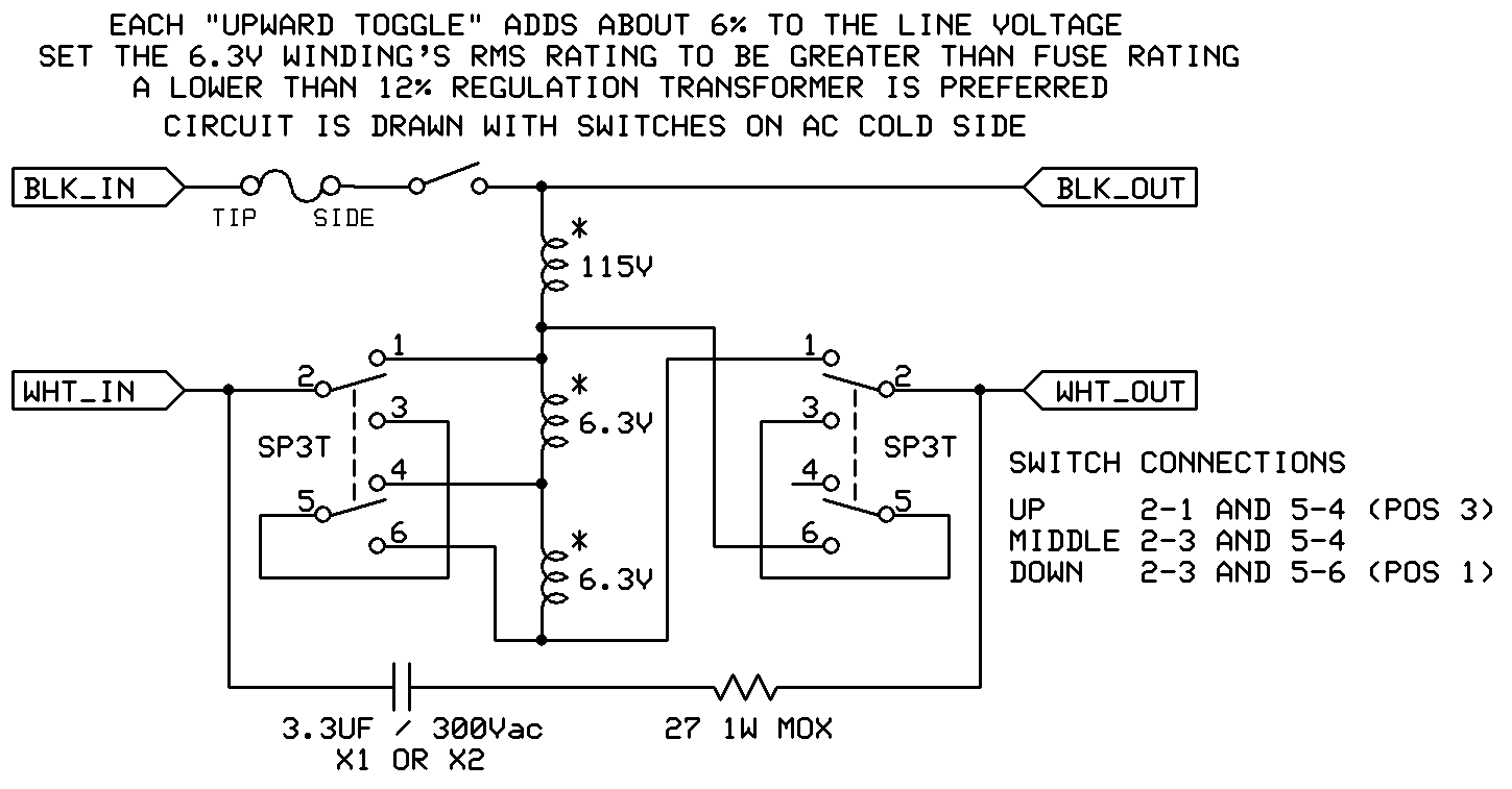
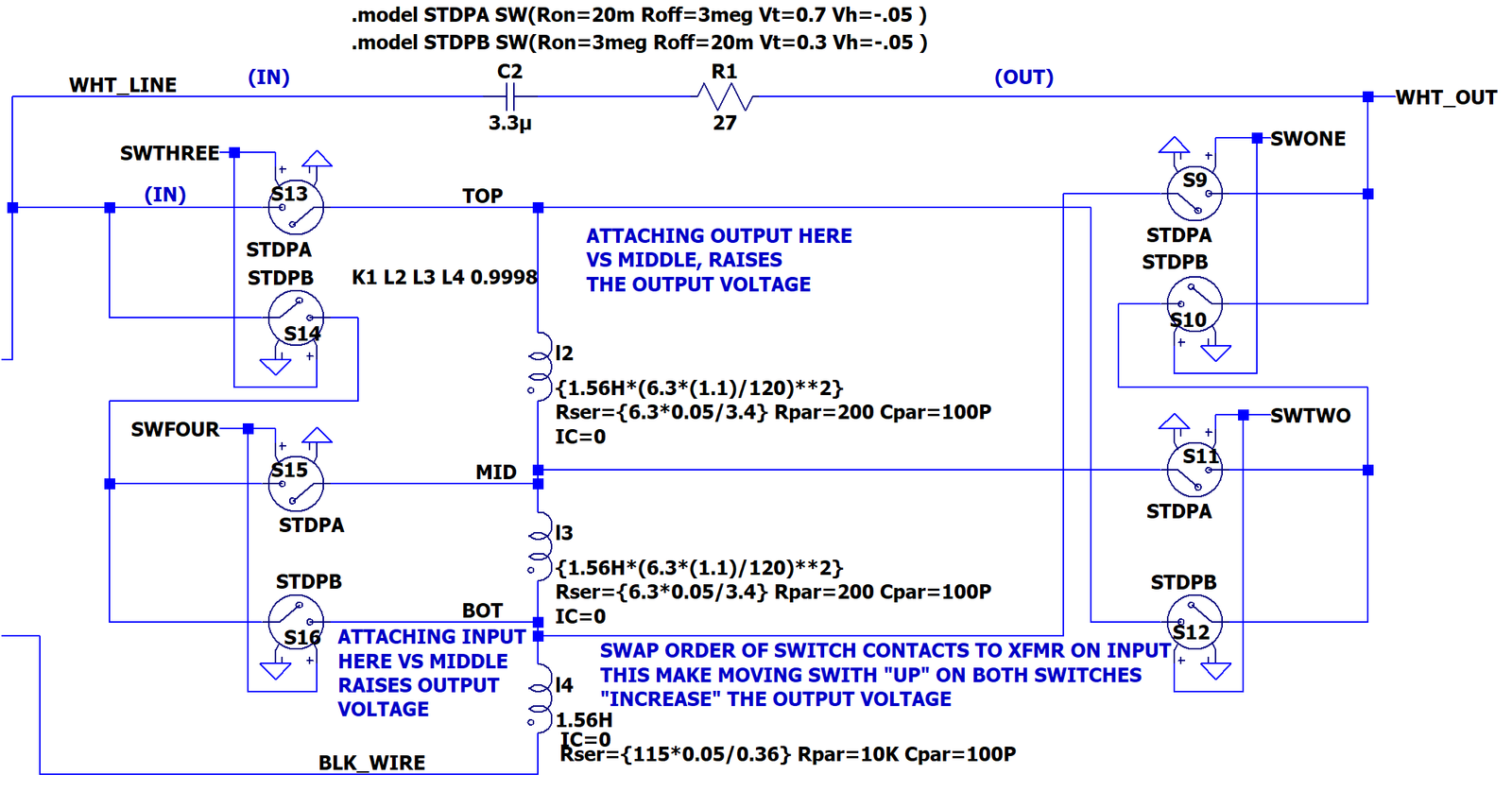
What we are building is 5-Tap "Switched Selected Autoformer." An autoformer works like any other transformers in that
Power Out = Power In - Losses.
There is an RC snubber from input to output to control the inductive kick when the switches are open. I don't expect to have both move switches at the same exact time which means we can get by with one RC snubber. If you are planning on moving both switches at the same time, you'll want 2 RC snubbers with the 2nd one going from line input to the 6.3V end winding.
With two SP3T switches (Single Pole Triple Throw), we'll have 9 combinations of switch positions.
3 Positions that don't change the output voltage.
2 Positions that raise the output voltage 6%.
2 Positions that lower the output voltage 6%.
1 Position that raises the output voltage 12%. (Input Up, Output Up)
1 Position that lowers the output voltage 12%. (Input Down, Output Down)
The positions with "Duplicates" work nearly the same between the duplicates with the biggest difference between them being in the power losses of the autoformer circuit.
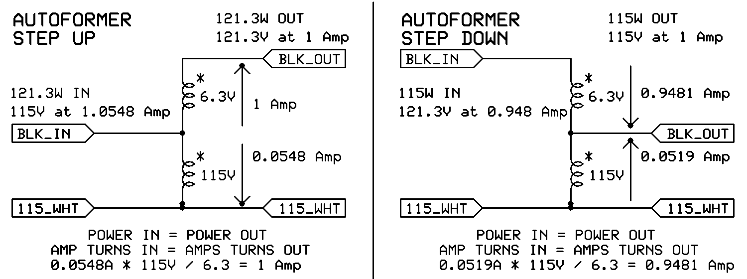
For the left example, start with the secondary voltage (6.3V) pin that connects to only one wire on the transformer.
With 115V applied to the primary, the 6.3V winding will raise the output voltage to 121.3V.
115Vac applied * (115V rating + 6.3V rating)/115V rating = 121.3V output
With the output at 121.3V, measurements/calculations show that the current draw is 1 amp for 121.3W output.
The input power equals the output power, 121.3W. Calculate the 115V current: 121.3W/115V = 1.0548A.
The current not going out the secondary (1.0548A - 1 amp) will be flowing through the primary winding (0.0548A).
A 12% Voltage change on the power bus often leads to a 12% change in your amp's B+; which comes with a 12% change in the tube's bias current. A 12% change in B+ is the difference between 10W on a tube and 12.5W in a tube.
After tuning your circuit up with a 120Vac input, you can trim the voltage to about +/- 3% of 120V over a 108 to 132Vac static line voltage range. If desired, you can use the line voltage step down for a "low loss" downward adjustment of your B+.
Pros of manually trimming the line voltage:
You can make your bias point the same at a friend's house as was at your house.
You can push the tube dissipation closer to maximum.
You can avoid any heat sinks needed for a linear regulator.
You can avoid any noise made by a switching voltage regulator.
After trimming the line voltage, the amp will run more consistently and at the same temperature (until the line voltage moves.)
The circuit is simpler when compared to automatic voltage adjustments.
Switches and a filament transformer are cheaper than a Variac.
Cons of manually trimming the line voltage:
You have to have a way to monitor your bias point.
You occasionally have to mess with the switch settings.
You'll pick up the heating losses of the 12Vct transformer you used. But, the amp should be running cooler.
This is not "automatic" and it is not "exactly perfect."
This doesn't automatically correct for B+ changes from tube current changes, it only addresses line voltage changes.
Yes, you can make it work on a 240V line, you just buy a different transformer and different resistor. I'd also use a higher voltage rated capacitor.
With 120Vac input, why do I only suggest an optional downward adjustment of the output voltage? This is because the line transformer in your amp may overheat with 132Vac applied to it and your filament's life expectancy will be shorter because they'll be running quite hot.
This is the least expensive, not PC board mount, 3 position switch I could find at Digikey in early June 2026. The E-Switch 100DP6T1B1M1QEH has a 5A resistive load rating at 120Vac. It has an electrical life of 6000 full power switches.
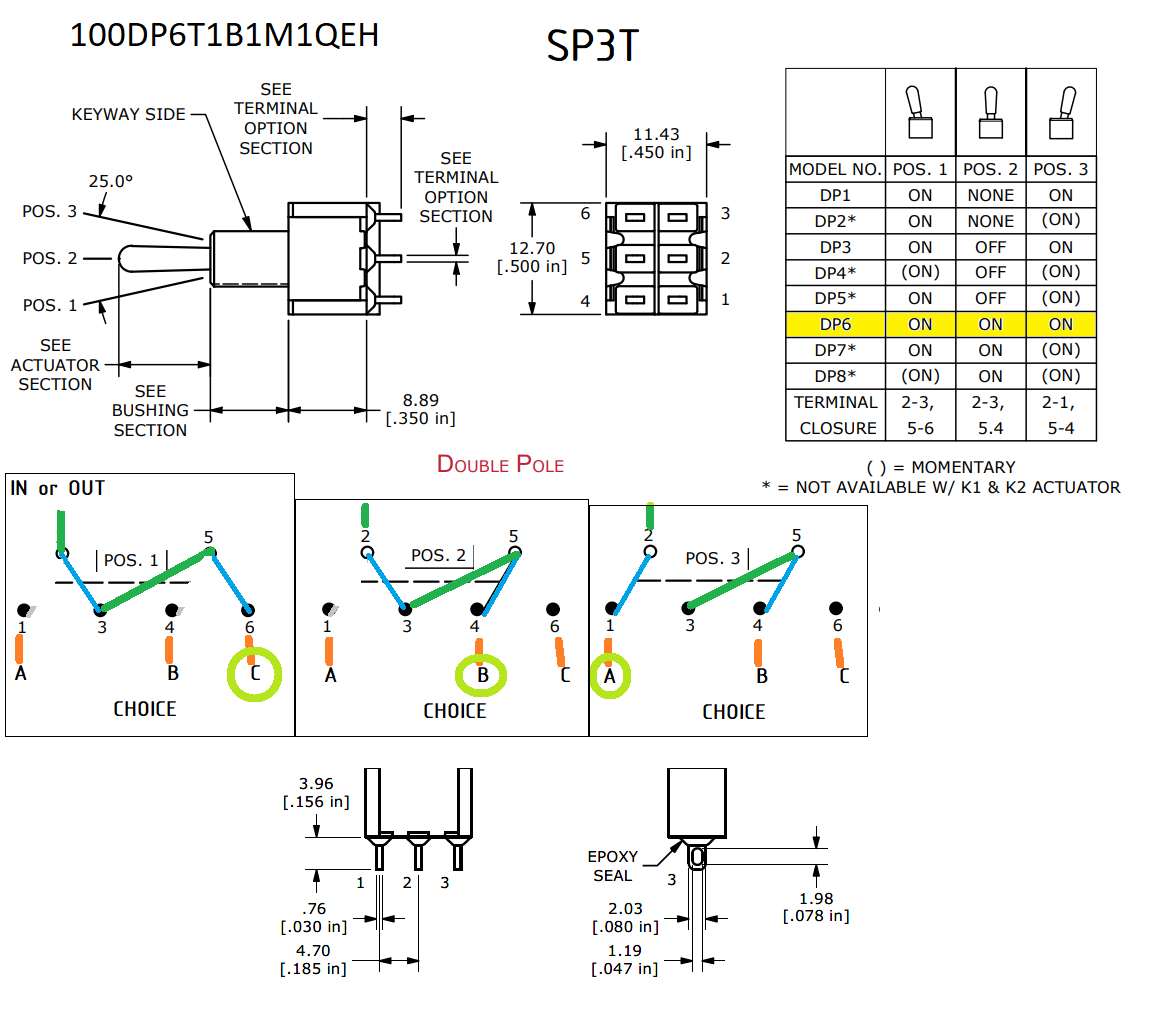
Depending on which wire table you look at, #22 to #24 solid wire is needed for 5 amps. You can fit two #22 in the eyelet for this switch. I would not mount the RC network directly to the switch, I'd use terminal strips or a PWB for that. Use wires with "real" insulation on them, not plain magnet wire.
The switch must be rated for both your line voltage and rated for at least the fuse rating used before the switches. Normally this is the same fuse rating as used in your amplifier. The fuse is often picked at 1.3 to 2X the steady state amplifier current draw. I picked a 5 amp rating in the E-Switch 100DP6T1B1M1QEH 120Vac switch ($6.72, the other switches were more than $10 higher in price per switch).
The transformer should have 2 windings or a center tapped secondary.
The transformer's secondary should be rated for the fuse rating of your amplifier. Missing it by 20% may be OK, missing it by 40% is not OK.
You'll want a transformer with good regulation (less than 12%, not 20% or higher.)
Buy a 50Hz transformer over a 60Hz transformer, they'll run cooler and quieter when used at 60Hz.
Buy a 120V primary winding over a 115V winding (it will run cooler).
For a 108 to 132Vac input range, with the output adjusted to 120V +/- 3%, buy a transformer with a 12.6V center tapped secondary.
If you want to only adjust an input range of 114V to 126V, buy a 6.3Vac CT winding.
The Triad VPS12-6300 at $31 is disqualified because of the 25% regulation (3.15V rise at no load).
The Hammond 183K12 at $25 is only 4.4A (we could switch to a 4A fuse). It doesn't list regulation but similar Hammond parts run 10 to 12% regulation. This is PCB mount part.
The Hammond 185F12 at $47 is 10.3 amps. It doesn't list regulation but similar Hammond parts run 10% regulation. Google believes it is 18% regulation. This is a screw mounted part (chassis mounted ). Because the part can handle 2X the current we need, the output impedance will be acceptable, but it will work more like a 6.4V * (1 +18%/2) = 6.93V per winding part. I can live with this. 185F12 PDF
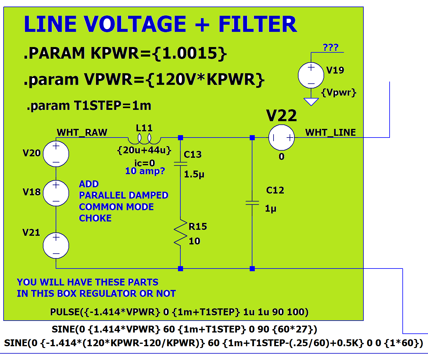
The capacitor value has many constraints and requires a lot of math. We'll assume the load's stored energy is close to the 12.6V transformer's stored energy.
Inductance of transformer approx = 120Vac/0.20A typical Imag / (2*pi*60Hz) = 1.59H
Energy in inductance = 0.5 * 1.59H * (0.2A*1.414)^2 = 63.6mJ
Capacitor value desired
Peak Voltage desired on cap = 132V * sqrt(2) =186V.
In a pinch, on a 300Vac rated cap, we could go to sqrt(2) * 300Vac = 424V.
Cap wanted approx = 63.6mJ/ (0.5 * 186V^2) = 3.65uF
Cap wanted approx = 63.6mJ/ (0.5 * 200V^2) = 3.18uF if we push the peak voltage a bit.
Cap required approx = 63.6mJ/ (0.5 * 424V^2)/0.9 tol = 0.786uF, round up to 0.82uF.
0.82uF is the value allowed if you want to take high risks. (Use the 3.3uF)
Use 3.3uF, use X1 or X2 capacitor (300Vac)
Irms through 3.3uF cap at 120Vac = 120V*377*3.3uF = 0.149A rms
377 = 2 * PI * 60Hz
Possibly use a TDK B32924D3335K000 3.3uF 305Vac 31.5mm x 16mm x 32mm X2 Box capacitor ($2.28).
Resistor value = High Line Voltage / Switch Contact Rating (132V/5A = 26.4 ohm) use a 27 ohm MOX flameproof part
Resistor wattage = 27 ohm * 0.149A^2 = 0.601W. Use a 1W rating so if switch goes open, there is no smoke.
Possibly use the TE Connectivity ROX1SJ27R ($0.11).
I had to experiment with the switch model to get a reasonable dead-band from a slowly rising voltage to the switch input. Reasonable means a model that didn't make LTSPICE "explode" with 7000 amps of current flow and megavolts peak when the switch opened. The trick was to
Add DC resistance to each inductor,
Set the initial conditions of each inductor to be "zero" using the .IC I(L1)=0 method, not the IC=0 in the part listing,
Make the switches open and close reasonably "gently" by using a negative hysteresis voltage.
.model STDPA SW(Ron=20m Roff=3meg Vt=0.7 Vh=-0.05)
.model STDPB SW(Ron=3meg Roff=20m Vt=0.3 Vh=-0.05)
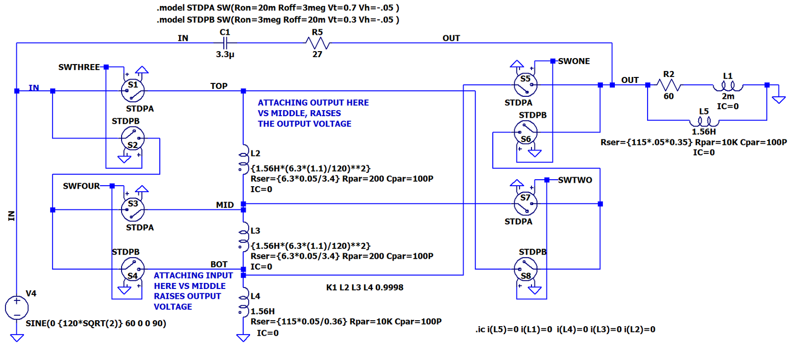
While there are 3 switch positions in the real switch, in LTSPICE there are actually 4 states. The output states are lettered with lower case letters a, b, c, d and the input states are in upper case letters A, B, C D.
You can see that the "Output voltage" does not always change when the switch states are moved.
The good news is that there are no super high voltage spikes and no super high current spikes predicted by the mode. We were shooting for just under 200V peaks and less than 5A current spikes. We met both goals.
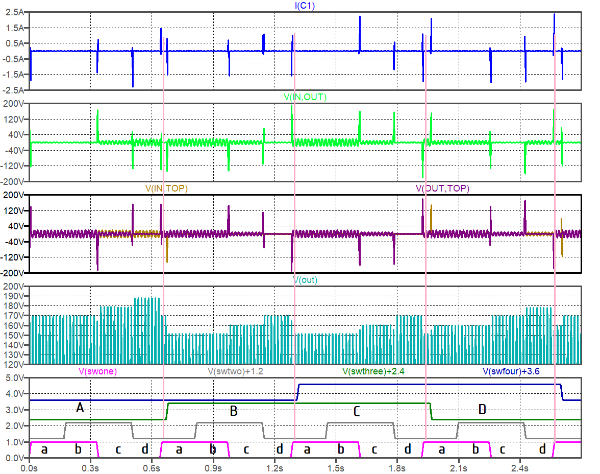
We saw we can flip the switches and get different AC voltages out, but does this actually do anything useful? Well, yes it does. Let's take the basic 500V output from the Basic 500V reference supply from the Half Baked Primary Side Regulator. The boxes in green are what we normally would build for an unregulated or un-adjusted power supply. The part not in the green boxes are what we are adding to make the performance better.
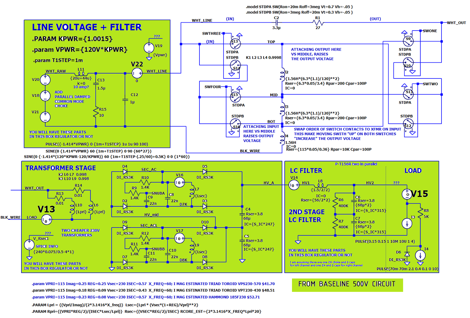
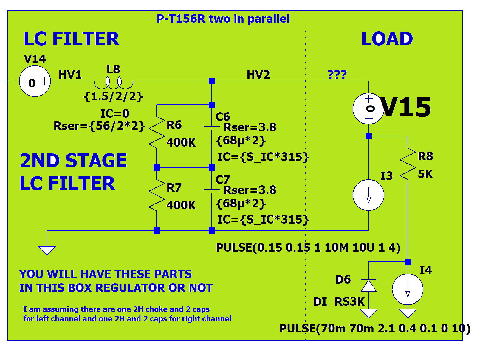
First is the power from the wall socket feeding a simple LC line filter. The baseline used the simple LC filter, so I'm using it here. The LTSPICE run will not be changing the input voltage, but we will be changing switch positions.
Enter the switch arrangement we studied earlier. But, we'll place the switches on the 115V Cold side of the circuit.
This feeds the transformer rectifier circuit that uses two cheaper transformers to make more than 500Vdc at 220mA.
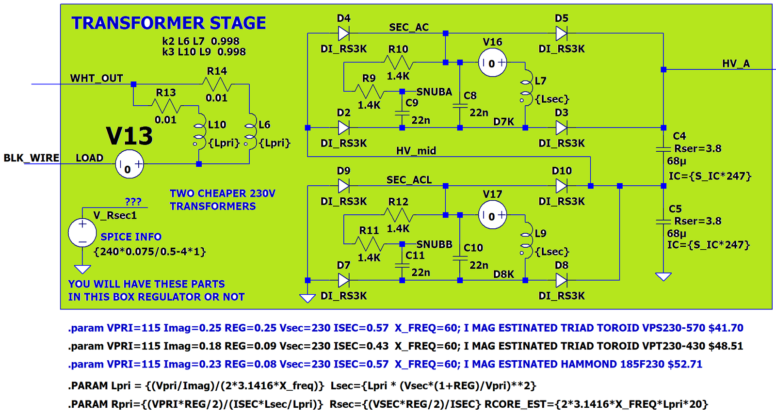
Then there is the final B+ LC filter and the load circuit. The load isn't doing anything fancy right now. It is just making all the other parts feel warm and toasty.
The DC output with the switch position changes looks like this:
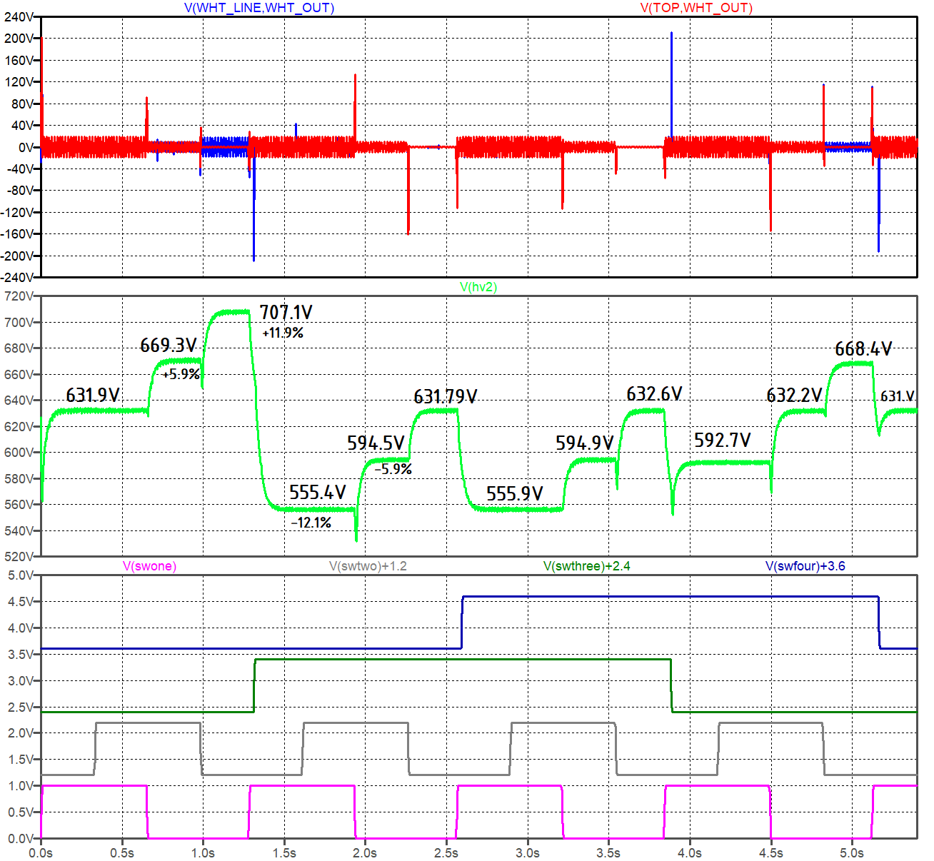
Great news: the voltage spikes are well controlled.
We also get a +/- 12% adjust range on the DC output.
Using a step-up on 120V power line to adjust the 120V to the equivalent of a 132 V into the amp is not a good idea if you are feeding a 60Hz transformer inside the amp from at 60Hz line. If you have a 50Hz transformer inside the amp and are running a 60Hz line, it can feed it with 132Vac, that is if the capacitors in the amp can take the additional voltage.
For those of you in 50Hz countries, not much can be done to help you. The transformer manufactures run the gauss high in power line transformers. The current spikes from the power transformer at the zero volt crossings are often higher than the current spikes from charging the high voltage capacitor bank. Using this DIY autoformer to raise a 108V line voltage back to 120V or lower a 132Vac input back to 120V is what we want to do with this design. It's perfectly OK to take 120V down to 108V if that is what your amp wants to have for good operation.
A 12% Voltage change on the power bus often leads to a 12% change in your amp B+; which comes with a 12% change in the tube's bias current. A 12% change in B+ is the difference between 10W on a tube and 12.5W in a tube. (The power change in the tube goes by the square of the change in voltage, (1 + 12%)^2 = 1.25:1. ) With this circuit, we can adjust most of that variation out.
If you aren't expecting to have to adjust over a +/-10% line voltage variation, you could change the 12.6Vct secondary for a 6.3Vct secondary and trim in 3% steps instead of 6% steps.
First version 3-Oct-2025, last update 3-Oct-2025.
Changes to correct font or spelling issues won't count as an update.
.
 ( New 2024 index page.)
 _( Old 2003 index
page.)
_( Old 2003 index
page.)
 _( AMP Second index page.)
( Fancy index page.)
_( AMP Second index page.)
( Fancy index page.)
.