
The DisChargeInator!
July 2024, Ver 0.1
It is a contraption who job it is that when the power line is shut off, it automatically drops a power resistor across the output of the power supply to discharge the capacitors in the power supply.
Some of us like abnormally large capacitor banks. We'll need to get the power supply voltage down on these large cap banks to a safer level some how before that stored energy can hurt us. At one point I had a cap bank that stored more than a kilojoule. It was scary! I used a switched 2 kW bank of resistors to discharge it. When parts hooked to that bank failed, they rapidly disassembled with a passion!
Like me, you could be working around the B+ with the tubes pulled, you'll want to have a way to automatically discharge the power supply voltage to a relatively safe voltage in a relatively short amount of time. With out the tubes loading the supply, those caps can stay at high voltages for a long time, a really long time (think in terms of hours). With really large capacitor banks, the tubes even when installed may not pull current long enough to pull the charge out of the capacitors in a reasonable amount of time.
A discharge time of 60-300 seconds is too long for me to wait before I get my fingers in my amp to change tubes or change a part.
The NFPA and NEC recommend it.
The most important one. . .We'll build it BECAUSE it is THERE! ( Isn't that why we are into DIY. )
SAFE Voltage: 50V peak or less ( Google: UL Safe Voltage )
SAFE Energy: Per Google, NFPA 70E-2019 360.3 says to auto-discharge when the energy storage is:
< 100V and greater than 100 Joule
>=100V and greater than 1.0 Joule
>=400V and greater than 0.25 Joule
Energy in a capacitor is
J = 0.5 * Vmax^2 * Capacitance in Farads * ( 1 + capacitor tolerance )
Reasonable amount of time: Per Google: NEC 480-6 and 480-28 say
A working voltage less than or equal to 600V needs to automatically discharge to less than 50V in 60 seconds.
Knowing that V(time) = Vstart * e^(-time/RC),
600V dropping down to 50V is 2.49 RC time constants
60 seconds / 2.48 = 24.1 seconds
maximum RC constant (i.e. Max cap tolerance and Max Resistor
tolerance.)
Example:
11.6uF ( max) at 590V is 2.02J.
24.1 seconds/11.6uF = 2.02meg max bleeder, at
5% resistor value, use 1.91 megohm
A working voltage greater than 600V needs to automatically discharge to less than 50V in 300 seconds.
If we start at 1000V, dropping to 50V
takes 3.0 time constants
For 1000V this is an RC time constant of 100 seconds max
We want to wait for about a tenth of a second after the power is turned off before activating the load dump. This is so that power glitches don't cycle the voltage on the capacitors and possibly overheat the discharge resistors.
We want to quickly remove the resistor when power is applied and the capacitors are only partially discharged. Power glitches are on the power grid now and I don't expect them to get better with the switch away from fossil fuels.
It should work with a full wave bridge, voltage doubler or full wave CT configurations with minor changes.
Target maximum operating voltage: 800V Peak on an unloaded power supply voltage. This will be closer to 650V B+ when loaded. If you want more voltage, feel free to add more series resistors and a higher voltage capacitor and FET to scale the design up!
Why 800V peak?
In Phoenix I've had a wall socket voltage of 134V in my current home and 107V in my first home ( -11% to +12% from the 120V. ) The regulation of a higher power transformer runs around 7%. If I use an affordable 120 to 240V transformer in a voltage doubler at very light load, such as with no output tubes, I get: 240 * (1.12) * (1.07) * sqrt(2) * 2 = 814V peak and I'm willing to throw in 14V drop for diodes and little filtering to get down to 800V. (or even allow +10% for high line instead of +12%)
We should only have to change the 10W discharge resistor values for operation on voltages down to 200V. Changing other parts to optimize the performance should be optional.
Fit
on half of an ExpressPCB PCB. I don't care for point to point
wiring anymore and for about $100 I can get 3 boards from
ExpressPCB that I can cut in half to get 6 DisChargeInators or use
the other half of the card for something else (may be an
Inrush_limit_Inator.)
The circuit should not do something bad if something breaks. This will require making some choices on parts and risks. The #1 risk is losing the sense wire to to the transformer. Doing that, the DisChargeInator will think the power is off and switch in the load dump resistors all the time. I'm only going to consider one bad thing happening at a time.
Here's the basic circuit:
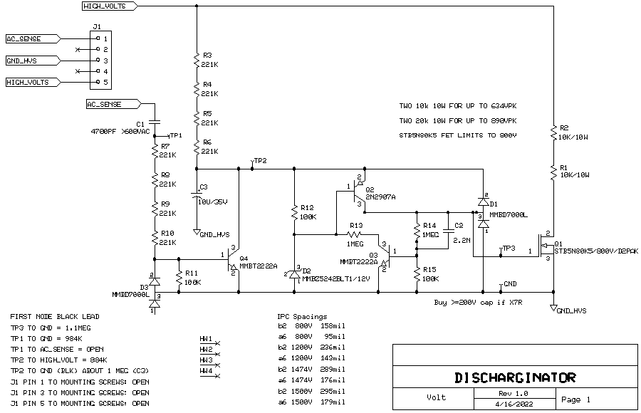
All resistors are standard 1 / 2 watt (200V).
Surface mount parts are called out. Be gentle soldering the SMT ceramic capacitors, pre-warm the ceramic and never hit the part directly with the iron. Heat the land and flow the solder to the cap.
Also, get your parts from a place that polices their parts like Digikey, Mouser etc. I've heard complaints about parts coming from Ebay and Amazon.
A zip of the ExpressPCB and LTSPICE Files shown on this web page.
1. With voltage on the "High_Volts", R3-R6 try to charge up C3, but every half cycle of the AC out of the power transformer turns Q4 on to discharge C3. Cap coupling through C1 makes this work with full bridges and half bridges. The size of C3 and the values of R3-R6 set the delay before the discharge resistor is connected to "High_Volts" We'd like this delay to be a few line cycles to avoid over heating parts with the line dips from large loads (air conditioning) kicking in.
2. When the Q4 discharge cycles stop, C3 charges up, The voltage gets high enough to turns on Q2 through D2 and this turns Q1 on. R1 and R2 limit the discharge current in Q1.
3. Q3 speeds the turn on of Q1 and provides hysteresis during the turn on event so that Q1 snaps on instead of "smooshing on." If Q1 snaps on, we don't have to worry about safe operating area or heat sinking.
4. D1 provides both gate voltage protection to Q1 and provides Vbe break down protection for Q2. Many FETs have so much capacitance from Drain to Gate, raising the drain voltage from zero to even less than full rated voltage can blow the FET out if there is no clamp from Gate to Source .
Part availability and part ratings!
1206 resistors are only good for 200V. Yes, high voltage 2520 resistors exist, but half the time they are un-obtainium. A normal 2520 resistor also won't take 800V. I need my resistors to be there to purchase when I need them, and not 34 weeks from now! Also, I wasn't going to risk someone using this circuit using a single 1W low voltage resistor that could fail after a few weeks of use. Using a resistor at higher than rated voltage is a risk to eventually get hurt at a later date.
The 221 Kohm 1206 resistors picked are rated for 200V, have multiple sources, are in stock every where and are are sold from well known companies to "Who the heck are they?" companies. The four 200V resistors handle the 800V OK and will work just fine. Having 200V across a 221K resistor is 181 mW ( 72% of rated ). At that stress level, it will last for decades.
For avoiding blue smoke in the design, there are three basic paths we can take:
At the maximum unloaded voltage the PBA will see, dissipate just less than 10W in each 10W resistor. Keep the 10W parts at least 1/4 inch away from anything heat sensitive. This results is a slower discharge time unless we decide to add off board 10W resistors to speed things up. If needed, adding more resistors that would survive during a fault (such as if the FET fails short) and adding more so that we meet the discharge time is my first choice.
Just bring the smoke, dissipate more than 10W and/or ignore the Joules ratings for the resistors. This path is strongly not advised.
Each 10W sand cast resistor is rated for 250J ( 5 time rated power for 5 seconds * 10 W ). A 25C rise in the cabinet knocks this rating down to 90% of initial.
Sanity check knowing:
Capacitive energy is 0.5 * Cmax * Vmax^2
Using two 10W 250J resistors on a 380V rail 500J * 90% at 380Vmax +20% capacitance supports a 6.23milliFarad (that's a big cap).
In normal operation, just bringing the smoke isn't too risky, but I still don't advise this route.
In this case, we want to round up on the bleeder resistor ohms to avoid hot smelling parts and accept a longer discharge time.
Unloaded voltage doubler will output 2 * 240V * sqrt(2) * 1.10 line regulation * 1.07 XFMR regulation = 799V
800V^2/ (2 x 10W ) = 32 Kohm / 2 resistors = 16K each
(round up to 20K each because the parts run hot)
The loaded voltage will be less than 800V, but I don't recommend taking the risk of using less than 16 Kohm.
The top schematic is a voltage doubler is using option 3 for the discharge resistor
The bottom schematic is a Fullwave CT is using option 1 for the discharge resistor

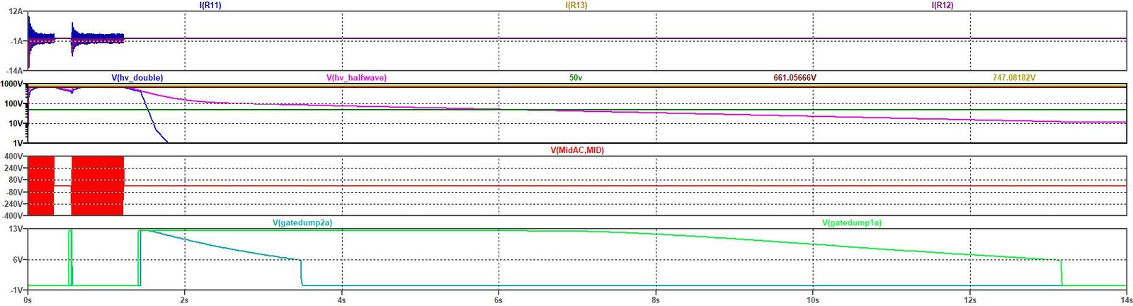
This first plot shows that option 3 quickly discharges the capacitor bank V(HV_Double) Blue. The gates stayed on until 12V (nominal) on the HV rail.
In this top graph i(R11) we see that
it takes a 1/2 power cycle for the gate to get turned off once
it is on and there is about a 200msec delay before the gates turn on.
The peak current on restart are essentially the same as at first power
up. The 4700pF 884K discharge detector starts to work at 8.3787v peak
or 5.9V RMS so it is compatible with just about any tube amp.

I chose to use a 2 layer board with the 10W parts and terminal block on the silk screen side. I plan on using a pair of #2 pencils to space the 10W resistors off the top of the Printed Board (PB) Note: I prefer using PWB for Printed Wiring Board instead of Printed Board, but that is the old fashion name. . .
The top copper looks like this before it is duplicated to make two per PB:
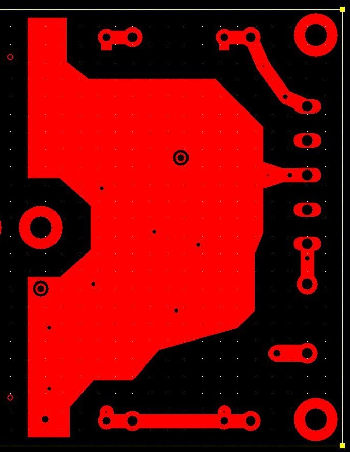
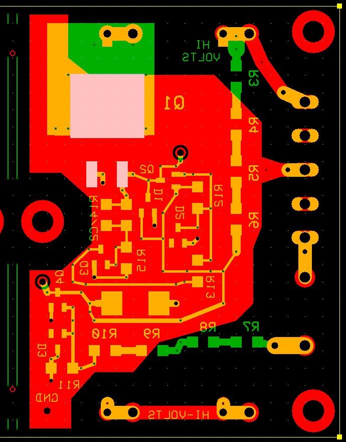
The X-Ray view of the top and bottom copper looks like this:
The Two small holes on the left and the green lines are my Scribe Lines to score the board two dozen times with a box cutter to split the one ExpressPCB PB into two. Always scribe before soldering and Blue Painters tape over the board during the cutting operation to protect the traces and lands.
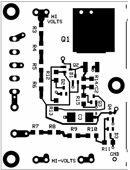
The Human Soldering View.
I don't have an assembled one to show you yet. This is planned to be used in a fancy SET I'm still working on.
The planned Parts List:
|
Qty |
Name |
Order |
Part ID |
|
1 |
4700PF >600VAC |
399-R76TF14705050J-ND |
C1 |
|
1 |
2.2N |
445-5854-1-ND |
C2 |
|
1 |
10U/35V |
718-T50D106M035C0120CT-ND |
C3 |
|
2 |
MMBD7000L |
MMBD7000LT1INCT-ND |
D1,D3 |
|
1 |
MMBZ5242BLT1/12V |
MMBZ5242BLT1GOSCT-ND |
D2 |
|
1 |
AMP 5 MM |
TO0501510000G-ND |
J1 |
|
1 |
STB5N80K5/800V/D2PAK |
497-16923-1-ND |
Q1 |
|
1 |
2N2907A |
MMBT2907ALT1GOSCT-ND_SOT23 |
Q2 |
|
2 |
MMBT2222A |
MMBT2222A-FDICT-ND |
Q3,Q4 |
|
2 |
10K/10W |
2368-10W310-ND |
R1,R2 |
|
8 |
221K |
RMCF1206FG221KCT-ND |
R10,R3,R4,R5,R6,R7,R8,R9 |
|
3 |
100K |
541-CRCW1206100KFKEBCT-ND |
R11,R12,R15 |
|
2 |
1MEG |
541-CRCW12061M00FKTACT-ND |
R13,R14 |
DUDE! STOP READING NOW
In the Appendices below I'm keeping my note book open for people who want nit pick the design. . .
Time to discharge desired = T1
Delay time before discharge starts = Td
Maximum initial voltage on capacitor = Vstart
Rnom discharge = (T1 - Td)/[-ln(50V/Vstart)]/(1+Cap tol)/(1+res tol)/Cnominal (farads)
If we just want to meet the NEC 60 second/5 minute limits with reasonable cap sizes, throwing away 2 watts of loss (a 5W resistor) in the bleeder resistor isn't that bad. When the capacitors get BIG or we don't want to wait a long time, then the bleeder resistors get to be a challenge if they are always attached.
|
Voltage |
uF |
Cap |
Joules |
Time |
Trigger |
Res |
Resistor |
Resistor |
Comment |
|
51 |
64078.0 |
20% |
100.00 |
60 |
0.50 |
5.0% |
37.2 |
0.07 |
100J Just over 50V |
|
100 |
16666.6 |
20% |
100.00 |
60 |
0.50 |
5.0% |
4.09 |
2.57 |
100J Limit at 100V |
|
101 |
163.3 |
20% |
1.00 |
60 |
0.50 |
5.0% |
411.3 |
0.03 |
1.0J Limit start point |
|
250 |
26.6 |
20% |
1.00 |
60 |
0.50 |
5.0% |
1103.0 |
0.06 |
|
|
399 |
10.5 |
20% |
1.00 |
60 |
0.50 |
5.0% |
2171.8 |
0.08 |
|
|
400 |
10.4 |
20% |
1.00 |
60 |
0.50 |
5.0% |
2180.0 |
0.08 |
|
|
401 |
2.6 |
20% |
0.25 |
60 |
0.50 |
5.0% |
8453.2 |
0.02 |
0.25J Limit start point |
|
600 |
1.2 |
20% |
0.25 |
60 |
0.50 |
5.0% |
16419.2 |
0.02 |
60 sec upper limit |
|
601 |
1.2 |
20% |
0.25 |
300 |
0.50 |
5.0% |
82864.8 |
0.00 |
300 sec lower limit |
|
250 |
364.7 |
20% |
13.68 |
60 |
0.50 |
5.0% |
80.5 |
0.82 |
one of my designs |
|
540 |
154.0 |
20% |
26.94 |
60 |
0.50 |
5.0% |
128.9 |
2.38 |
Another design |
|
540 |
154.0 |
20% |
26.94 |
10 |
0.50 |
5.0% |
20.6 |
14.88 |
|
|
540 |
154.0 |
20% |
26.94 |
19 |
0.50 |
5.0% |
40.1 |
7.64 |
|
|
540 |
256.0 |
20% |
44.79 |
16 |
0.50 |
5.0% |
20.2 |
15.16 |
|
|
540 |
1001.0 |
20% |
175.13 |
60 |
0.50 |
5.0% |
19.8 |
15.44 |
|
|
720 |
154.0 |
20% |
47.90 |
300 |
0.50 |
5.0% |
578.7 |
0.94 |
Another design |
|
720 |
154.0 |
20% |
47.90 |
15 |
0.50 |
5.0% |
28.0 |
19.43 |
|
|
720 |
256.0 |
20% |
79.63 |
10 |
0.50 |
5.0% |
11.0 |
49.29 |
|
|
720 |
256.0 |
20% |
79.63 |
24 |
0.50 |
5.0% |
27.3 |
19.93 |
|
|
800 |
154.0 |
20% |
59.14 |
22 |
0.50 |
5.0% |
40.0 |
16.82 |
With four 221K resistors in the two strings of 4, the circuit nominally starts to work (just barely works) at 34V peak out of the transformer. For better performance at voltages less than 800V peak (unloaded), remove one 221K in each of the two strings of four parts for every 200V below 800Vpk. The unloaded voltage is what drives the number of resistors, not the nominal. This really isn't needed, but I know someone is going to ask.
For about 24V to 99V nominal (200V unloaded) use one 221K resistor
For about 100 to maybe 299V nominal (400V unloaded) use two 221K resistors
For about 300 to maybe 499V nominal (600V unloaded) use three 221K resistors
For about 500 to maybe 700V nominal (800V unloaded ) use four 221K resistors
After the first cut on the number of resistors, put the design into LTSPICE and see if it behaves like you want it to.
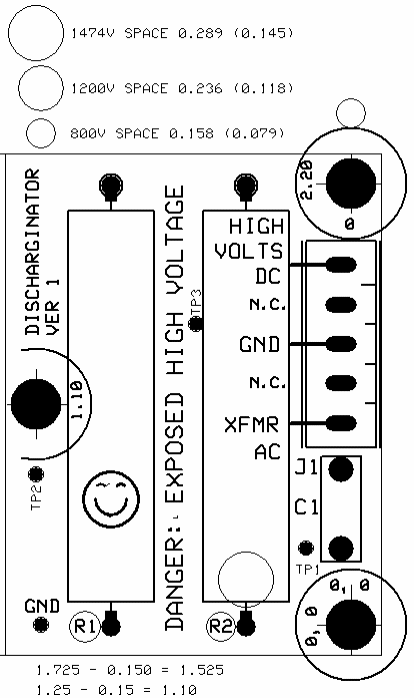
The resistor side of the AC sense capacitor will have +/- 700V with respect to ground on it when used with an unloaded full wave center tap making 800V DC output. This is 1500V between the resistor solder joint and the +800V.
|
Voltage |
IPC B2 Spacing, Mils Trace trace, uncoated |
IPC A6 Spacing, Mils Lead to Lead, uncoated |
Spacing Used, Mils (
Radius of Checking Circle |
|---|---|---|---|
|
1500V pk |
295 |
179 |
289 (145) |
|
1200V pk |
236 |
143 |
236 (115) |
|
800V pk |
158 |
95 |
158 (76) |
|
200V pk |
49.2 (1) |
31.5 |
49 (22) |
On a super clean PB, 50 mil spacing arcs (fails) at 2 kVpk (tested) give or take a bit, but our boards won't be clean for long so don't use 50 mil spacing for voltage much over 200V.
To do, add in pollution degrees data. . .
The MOSFET basically needs to be a D2PAK or larger rated for >=800V. I've had issues at work where a part is rated for higher voltages (like the 800V DPAKs out there) but the lands on the printed wiring board (PB) won't support the voltage.
The diodes are picked to be SOT-23-3 parts. The 100 mil spacing on SOT-23-3 are easy to solder and it is hard to install the part backwards. However, you have to be a PRO to solder SOT-23-6 parts, the tight spacing makes it easy to make solder bridges.
Other passives that are 0805, 1206, 1210 are also easy to solder. 1812 resistors are OK, but 1812s are starting to get "delicate" if they are ceramic capacitors. 1825, 2512, 2220 ceramics capacitor are just failures waiting to happen even when soldered with a hot air pencil. You don't preheat the ceramic capacitors or you flex the board, they crack and just when you want to impress some friends, they crack causes a short and the part FAILs. 0603 are OK for experienced solders to work on, but 0402 and smaller and fine pitched SOICs are simply evil to work with by hand.
The circuit needs a >800V capacitor for the AC sense. Large package ceramics where off the table because of the risk of cracking. SMT film capacitors were also off the table, some of the SMT films go through a Clearing process at first power up (blowing out shorts). During installation, unless you are very careful, the SMT film part will be damaged (melted) in soldering. So, I'll wimp out and use a leaded film capacitor for this.
The impedance of the AC coupling capacitor should be slightly smaller than the impedance of the resistors in series.
1/(2 * PI * 60 Hz * 884K ) = 3 nF at 60 Hz
I'm going to round this up to 4700 nF this was in stock, 3.3 nF was not.
On the SMT parts, use water or IPA soluble flux on every solder joint. This isn't the flux in the core of the solder. This is flux you apply yourself through a small bottle.
After soldering, clean the PBA after soldering! 90% IPA works nicely, but clean it outside. 90% IPA is flammable, 70%, not so much. Clean even with no-clean fluxes. This is high voltage and is something we want to last 20 years, not to the end of a 30 day warranty.
In this case we want to round down slightly to avoid the hot smelling parts.
The normal high line output voltage will be 716V output at 123 mAdc, 88W output + 20W for filaments. The line fuse will likely be for 20% more than that.
108W/ 0.8 /120 V = 1.12A (we'll use 1.25A)
Caution: Because the variation is so high in the energy at the 1 second blow current for the fuse, we need to shoot for the 0.1 second blow time current, 3.6A. Even at 3.6 amps on a 1.25A fuse, it nominally opens in 0.1 sec but could take longer. This would deliver about 43 to 360 joules into the load. Two 10W sandcast resistors can accept 500J.
120V*3.6A/(716V *( 1 - 20%) ) = 432W / 572V = 0.75A or 758 ohms on B+
Nearest value is two 360 ohms. Plugging this into Duncan Amps PSUDII, we get 2A on the 120V and the diodes (I(D1) in the HV supply are seeing more than 1.2A (The diodes likely need to be rated for 2A)
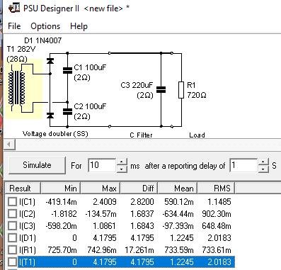
A couple of iterations in PSUDII gets us to two 130 ohm (260 ohm) which pulls 3.6A on the primary. The Diodes (D1) are seeing 2.4A at this point. This really doesn't look like a very viable solution

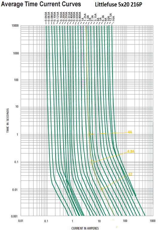
From
the fuse curves we see these values and we see that a small change in
current leads to a large change in Joules. For the fuse to offer
decent protection, the fault current has to be considerably higher
than 3X the fuse rating. If we want the fuse rating to be
derated 5%, we are looking at faults should draw more than 4X normal
current OR better said: The circuits in the fault path have to take
more than 4X normal current draw.
|
FUSE Rating |
120V Watts |
100ms Amps |
1 Sec Amps |
100msec Joules let-through |
1 sec Joules let-through |
100msec Amps / rating |
|
1 |
120 |
2.7 |
2.3 |
32.4 |
276 |
2.70:1 |
|
1.25 |
150 |
3.6 |
3 |
43.2 |
360 |
2.88:1 |
|
1.6 |
192 |
4.8 |
4 |
57.6 |
480 |
3.00:1 |
First version 5-Jun-2024, Last update 30-July-2024.
Yes in Aug I made a change to correct a couple font issues, that
doesn't count as an update.
9-11-2025
added the ZIP file with the expressPCB and LTSPICE files.
 ( New
2024 index page.)
( New
2024 index page.)
 _( Old 2003 index page.)
 _( AMP Second index
page.)
( Fancy index page.)
_( AMP Second index
page.)
( Fancy index page.)