Tube
Calculator
Last
update
10 Aug 2024
2003
Tube DIY
Current
Tube DIY
Evil
DIY Twin:
AmpSecond
Paralleled
Tubes V2
Single Ended
Tube amp
Pre-load
Ratings
per Tube:
^- Rated Watts
^- Rated Volts
^- Ib0mA
Onset of Current Distortion
Enter Tube
Constants:
^- ohms
R_Plate
At Vgrid=0V
^- Ib0mA Used
Trade Less
Power
for less Distortion
^- Ebmin Used
If not
known
use 10% of
Rated Volts
Enter
Tube Load:
^-# Parallel tubes
^- Ohms Total
Primary Load
^- Desired plate
watts per tube
Calculate
Plate Loss
Eb1 Check
RDH
Best Load Ohms
HEADS UP !
Calculated
Results
ARE NOT
UPDATED
when the
Pre-Load
button
is pressed.
Re-click the
Calculate
button
to update
the Results.
| Load Per Tube |
Best Damp ing Factor |
Plate Loss Per Tube |
% Rated Watts |
Best lb1 mA per Tube |
Best Vbias (Eb1) volts |
Eb1 check |
Vrms on plate |
Pout watts per tube |
Pout watts total |
Total mA Out pk-pk |
|---|---|---|---|---|---|---|---|---|---|---|
. .
. .
. .
. .
. .

..
First use the pull down menu above the "Pre-load" button to pick a tube
and then click on the "Pre-load" button to load the tube data and a suggested load,
or just enter all the tube data and tube loading yourself.
Second, click on the "Calculate" button.
Clicking on the "Calculate" button fills the table and plots the plot.
When looking at the output power, remember that our ears hear volume logarithmically. For something to sound twice as loud requires ten times the power (10dB). A 20% difference in power is 0.8dB. That amount isn't a change in volume, but if that power difference is located in one frequency range, it can be a difference in "tone." Keep an eye on the DF (Damping Factor), for that impacts the "tone" or sound of bass frequencies and impacts how the speaker performs at its crossover's impedance peaks and dips.
The calculator outputs three different bias points for a given load impedance.
The second is with all tubes running at 100% of rated power which can cause the Eb1 bias voltage to exceed the rating for tube.
The third is at 100% of rated plate voltage for the tube. This bias point can cause the steady state power loss to exceed what is rated for the tube.
On the bottom left, there is a suggested "RDH (Radiotron Designer's Handbook)" Best Load" resistance that will get you close to the maximum output power for the group of tubes being used. I prefer to use something 33-50% higher than this in order to deal with 8 ohm speakers being closer to 6 ohms in real life (i.e. use a 6800 to 7500 ohm transformer instead of the recommended 5000 ohm transformer.) The RDH best load resistance value will change if you change the number of tubes in parallel. To see the new number, you'll have to hit "CALCULATE" again. The "pre-loaded" values automatically display the RDH best load, but if the plate dissipation or number of tubes in parallel is changed, the total load resistance on the bank of tubes will not automatically update. If the recommended RDH value is negative, lower Ib0. You may also need to adjust Ebmin if you don't like the results.
The DF (Damping Factor) is primary side damping factor that assumes that the output transformer is wound with super conducting (zero ohm) wire on the primary and secondary windings. We can't buy this part yet. As an approximation, when the primary resistance of the transformer is 1/4 the effective plate resistance of the tube, you are at the point of diminishing returns. The effective plate resistance is the Rplate for one tube / the total number of tubes in parallel / any reduction in plate resistance from primary side feedback.
Reminders:
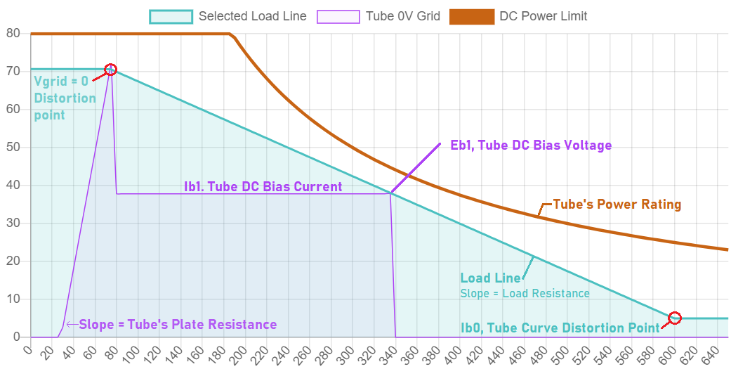
Ib1 is the DC steady state anode bias current.
Eb1 * Ib1 is your static DC power loss per tube. I recommend keeping this at least below 85% of the rated tube wattage, particularly with paralleled tubes. Also allow for plenty of air flow around the bank of paralleled tubes and insure each tube has its own Grid-Stop resistor.
Pout/Pbias is your plate efficiency. Single ended tubes are normally bias in class A. Anything over 30% (0.30) is "par for the course."

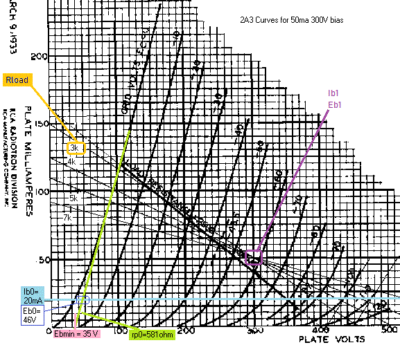
- The left sloped portion of the purple "Tube 0V Grid" line shows the curve fit for plate's V and I. The curve fit for the "Tube 0V Grid" line must have high accuracy above the Ib1 current, i.e. the dc bias point, for the equations to work. Don't worry about fitting data points for the curve down by the Ib0 current, your curve fit software will help you figure out what Ebmin should be. The "Tube 0V Grid" curve is the plate voltage and current with Vgrid = 0V which defines the tube's plate resistance at this grid voltage.
- After the turquoise colored "Load Line" curve hits the "Tube 0V Grid" line, Ib1 and Eb1 are then shown then on the purple "Tube 0V Grid" plot.
- Maximum output power occurs when the current swing from where the "Load Line" intersects the "Vgrid=0V line distortion point" to the "Ib1" bias point is equal to the current swing from "Ib1" bias point to the "Ib0" distortion point. This results in having the same output swing before distorting whether the current is going up or down from the DC bias point.
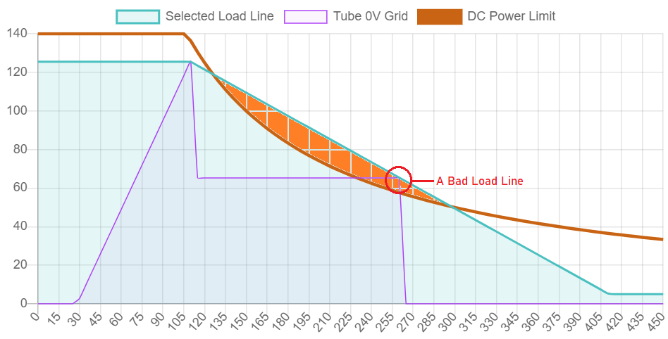
- The "Load Line" should be below the brown "Tube's Power Rating" at all voltages to avoid stressing the tube.
- The plots are calculated with finite voltage steps that change depending on the tube and the bias point. This can cause the plots to not perfectly match the data in the table.

Above is an example of a "Bad Load Line."
This means that if all of the plates read "zero ohms" to each other and all of the cathodes read "zero ohms" to each other, the circuit is not likely to bias up and to operate correctly unless the tubes are perfectly matched over temperature and aging. So with magically matched tubes, yes it will work, but magically matched tubes only exist in the modeling world.
With a normal SET, the recommended way to mitigate this is to tie all the plates together with a wire and give each cathode its own bias resistor (and bypass cap).
If using a Parafeed setup there is a different "option", each tube gets its own "high DCR" Plate Choke (or a CCS). Each plate then gets its own parafeed cap to the output transformer. That way the cathodes can be tied together and the output transformer can be connected to the cathodes.
.
Version 2
The site and script has minor edits by VoltSecond.
Send any questions or comments via emails to VoltSecond through the Tube Asylum.


