
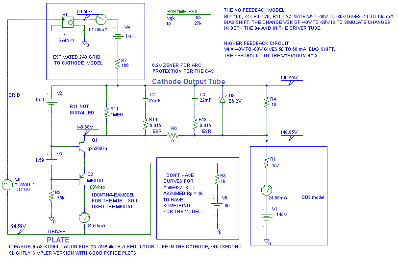
This is an idea to stabilize the bias point in a DC coupled SET with a
regulator tube in the cathode of the power tube. The actual output tube is
not shown. It is what is represented by the words "CATHODE OUTPUT TUBE"
and E1 with R7. How it works is if the bias current into the regulator
tube is too high, the circuit "LOWERS" the bias current to the driver
tube. If the Autobias is crosses over at a very low frequency AND do
anything squirrel-y, it should be any worse than a well designed subsonic
filter with respect to performance.
Q1 and Q2 are the transistors in a C4S current source. R4 is used as a current sense resistor to adjust the current into the plate of the driver tube. By adjusting the current into the plate of the driver tube, the grid voltage of the output tube is adjusted thus stabilizing the operating point.

I sent a version of this to Doc when he first talked about regulator tubes in the cathode of the output tube. I can't date the email since that was before my last major windows crash where I had to reload windows onto a freshly formatted disk.
R5, R6 and C1 provides extra attenuation to keep the stabilization loop out of the audio band.
D3 is a transorb to protect the C4S against tube arcs. This could be put across R11 to protect Q1 but R5 and R6 reduce the voltage even further the way it is drawn. It is important that Q1 does not have its base emitter junction reverse avalanched.
R5 provides some resistance in the emitter of Q1 to keep the C4S acting as a good current source.
R11, R5, R6, R12 and R4 set the amount of overall loop gain. The circuit above has very little loop gain on purpose.V6 and R8 are a simple model for the plate of a WE407 tube.
V1 and R1 are a simple model for an OD3 gas regulator tube.
Note: It is necessary to keep the peak to peak ripple at the emitter of Q1 to less than 25 mV with no load to full load flowing through the output tube for the loop to be fairly linear. Much less than this is appropriate to keep the bias stabilization out of the audio path.
This is the loop response for the above circuit with 1 V on V6 so that we can plot the loop response.
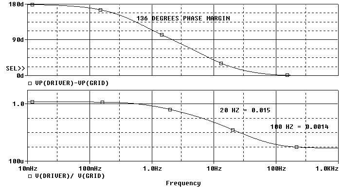
At 100 Hz, the loop is 20 log( 0.0014) = 57 dB down, I wish it was more.
Lets take C1 out of the loop by setting it equal to 0.1 uF:
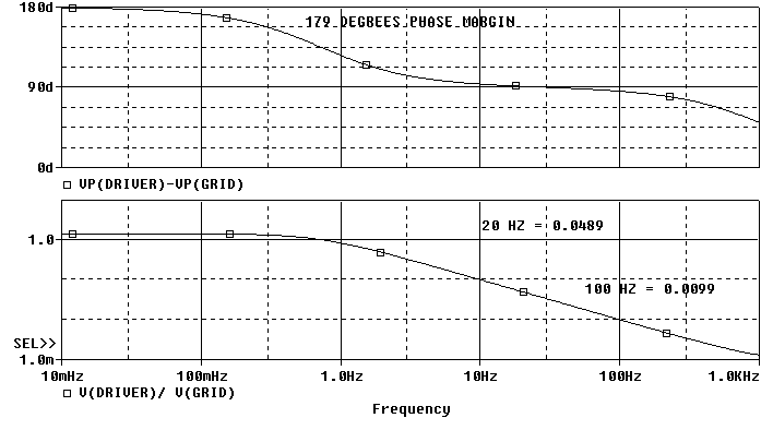
Now at 100 Hz, the loop is only 20 log (0.0099) = 40 dB down, 17 dB worse. Notice that the loop gain at 10 mHz stayed the same.
Digikey has a Panasonic 120,000 uF 16V that is 1.6 inch dia. by 3 inches long with 0.013 ohms ESR. I'd used two of them if I was building this circuit. I know Michael Percy has 15,000 uF 10V capacitors that will work with the original schematic above.
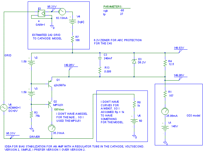
The loop response of the simple circuit is shown below. Notice that the circuit has much more loop gain at DC. That means the loop will track better, but it also means it can affect the audio path more. Having the capacitor on Q1's emitter drops the output impedance of the C4S from 600K down to 550K (no big deal).
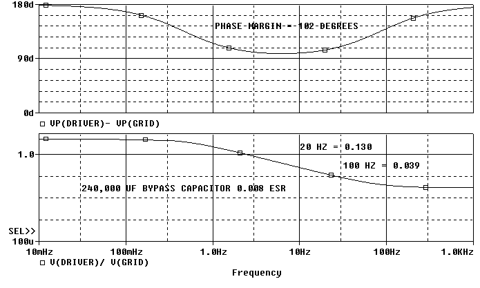
At 100 Hz, the loop is down 20 log (0.039) = -28 dB, not near enough in my book.
If you think the tube arc current (2A3 or OD3) will be less than 0.70 amps, D3 can be omitted.

At 100 Hz the loop is down 20 * log( 0.0047 ) = - 47 dB. This is not as much as the stock circuit because I included the capacitor ESR in the model.
Design notes:
The loop gain of this circuit is directly proportional to the Rp of the driver tube. If the driver tube's plate impedance doubles, the crossover point will go up approximately a factor of two. So if the crossover was at 4 Hz, it is now at 8 Hz. Since the poles are in the same locations, the phase margin will decrease as the crossover frequency goes up.
.
 ( New
2024 index page.)
 _( Old 2003 index page.)
 _( AMP Second index
page.)
 ( Fancy index page.)