Many times a tube enthusiast needs a 550V capacitor or higher but only has a 500V part available. I am offering ideas on how to do this below. Why would you want to stack unequal capacitors?
1. To get the maximum effective capacitance in the power supply when you are using a decorative bottom (ground side) capacitor.Keep in mind that when stacking capacitors in series, the cases of the capacitors will be live and can have lethal voltages on them. If the case isn't at ground, put it inside the chassis where fingers, dropped cables and wires can't touch it. Tie down and insulate the capacitors so that moving the chassis around doesn't cause them to wiggle, droop and cause a short from the High Voltage to something that won't like touching High Voltage.
2. To add a little voltage margin to a special capacitor ( like a low voltage Cerafine (TM) on top of a high voltage Cerafine (TM) .)
These high voltages can kill you. Wear rubber soled shoes to help keep any accidental shocks from passing through your body. Make sure the unit is unplugged and the capacitors are completely discharge before your body or tools come in contact with the equipment you are working on.Capacitors can vent (commonly know as exploding). Wear safety glasses when working with electronics, especially when working with capacitors. Wear two pairs the first time voltage is applied to a capacitor after soldering. If you care about what your face looks like, wear a complete face shield. Most of my friends have a scar or two somewhere on their body from working on electronics. I often put a nonflammable plastic box over my work the first time I apply power.
High energy capacitor banks (even low voltage ones) can make wire, necklaces, rings and watches glow white hot and if the conditions are right, the metal seems to explode. Do not have any metal on your body except possibly for your belt buckle (its hard to run for the fire extinguisher when your pants are falling down) and face shield (safety glasses.)Second, play smart (partial list).I prefer to wear long cotton pants. Solder drips burn through polyester and hurt for weeks. I don't wear either of my two wool pants when soldering because they cost too much to be ruined with a burn mark.
Work with a friend who knows CPR and knows how to pull the plug from the wall if you forgot to do that first.
Work with a full fire extinguisher in view. Do not put the fires extinguisher where you would have to reach across equipment to get to it.
The case of a capacitor can have voltage on it. Check it with a working voltmeter on both AC and DC before attempting to touch it.
Make sure you can pull the plug from the wall without having to reach over either the equipment you are testing or the test equipment. Yep, I've smoke test equipment in my time too.
Make sure you can exit the room rapidly without passing your equipment or tripping over piles of stuff on the floor should you need to run for it.
Make your own safety assessment. Your design and craftsmanship must be safe for both you and those who enter your house. Do you have any friends, relatives or acquaintances who insist on touching things when they say "what does this do?" Remember, U.S. law does not recognize "Darwinism" as a defense in court.
Both old and new parts can be defective. Test them before installing them.One atom of chlorine in an aluminum capacitor can ruin it. Chlorine is a catalyst that attacks the plates of the capacitor. Do not use chlorinated solvents on aluminum capacitors. The end seal on the capacitor reduces the risk of contamination, it does not eliminate the risk.
Aluminum capacitors dry out and their rated voltage drops with age. Reforming a capacitor can help fix the rated voltage drop, but it won't fix the life issue. Aluminum capacitors are wet inside. Drying out means just what it sounds like. Do you really want to spend your hard earned free time installing capacitors that will have to be replaced soon? Buy newer aluminum capacitors.
Make your own risk assessment. Read the application notes for the parts you are using. Generally, greater than 1/2 inch diameter aluminum caps 5 years old may be OK. Less than 1/2 inch diameter caps 5 years old I would not fool with. In my opinion, any aluminum cap over 10 years old should not be installed as a replacement part. In my opinion, there won't be enough life left in it to justify my labor and time. Look in the Digikey catalog at the life expectancy for the aluminum caps that are being sold. 2000 hrs at 85 to 105C is a typical. Keep in mind that one year is 8760 hours and the aluminum capacitor is drying out even when it is not being used. It used to be thought that the capacitor's life expectancy doubles every 10 C cooler you run the capacitor. Current data from a vendor (I can't find their web page back) says that the curve is not near that generous.
Watch out for tantalum capacitors. When they vent, they can spew molten tantalum!
In a capacitor,
V = Q/ C (voltage equals coulombs over farads.)
1 coulomb = 1 amp for 1 second.Since stacked capacitors are in series: at power up, power down and during tube arcs, all caps in the series chain see the same current for the same amount of time (ignoring the bleeder current.) Because the current and time are the same through every series cap, the charge is also the same in each capacitor. Knowing the charge is the same, you can actually add non equal capacitors, but you must be careful doing it.C effective = ( 1/ C1 + 1/ C2 . . . + 1/ Cn) for series capacitors.
ESR_effective = ESR_1 + ESR_2 . . . + ESR_n for series capacitors at mid frequencies.
Low frequencies are those frequencies where all of the capacitor's impedances are dominated by their capacitance.
Mid frequencies are those frequencies where all of the capacitor's impedances are dominated by their ESR (Equivalent Series Resistance.)
High frequencies are those frequencies where any of the capacitor's impedances are dominated by their ESL (Equivalent Series Inductance.)C effective = C1 + C2 . . . + Cn for parallel capacitors
ESR_effective = 1/ (1/ ESR_1 + 1/ ESR_2 . . . + 1/ ESR_n) for parallel capacitors at mid frequencies.
Also, keep in mind when stacking capacitors in series, the case of all the capacitors but the one with its case attached to ground will have HIGH VOLTAGE on it! Mark and insulate all of the hot case parts accordingly. Do not put hot case parts on the outside of a unit. Hot case parts always go on the inside of a unit and are marked so the next person knows that the case is hot. I recommend insulating finger guards over hot case capacitors even when they are inside a unit. You never know when a finger or wire will slip where it does not belong.
When you add non equal capacitors, you need to either keep the maximum ALLOWED charge close to constant in each capacitor or heavily derate the voltage on one or all of the capacitors to survive power up and faults. Again, by charge I am talking about:
coulombs = farads * volts = amps * seconds.I am recommending that either:
Q = C * V = I * T
( This actually should be the integral of current over time: which is the same as the average current times the seconds it was averaged over. )
1. The nominal C times rated V be the same on each capacitor because at power up or during an arc, nominal C times actual used V (charge) will be the same in each capacitor. OR
2. The nominal C times used V in each capacitor be equal to the smallest C time V rated for the series string of capacitors.
The balancing resistors also need to be picked hold the DC voltage on each
capacitor at a point that keeps the charge in each capacitor is the same.
The current flow through the balancing resistors should be 10 times the
leakage current of the leakiest capacitor in the stack. Some people use 5
times, some people use 20 times the actual amount. This padding is a risk
assessment you make during the design phase.
The balancing resistors can run hot. Don't place them in direct contact with the capacitors because that will shorten the capacitor's life expectancy.
Unless each capacitor can take full voltage and full surge current,
expect the entire capacitor string to fail if any one of the
capacitors in the string fail short. As soon as one capacitor fails short,
the others see more voltage stress which will cause them to fail.
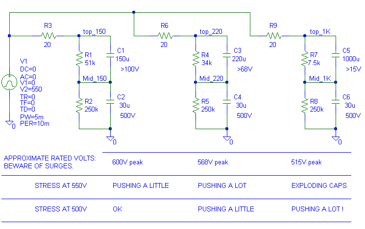
1. You have a 30 uF rated at 500V which equals 15 mC of charge storage. You are using the capacitor bank at 550V worst case peak during the turn on surge and you decide that you want a 600V peak rated capacitor. Lets add a 100V capacitor on top of the 500V capacitor to get the 600V rating.
The 100V capacitor value should be approximately 15 mC/ 100V = 150 uF.Lets say you want a 2 mA bleeder/balancing resistor.The actual total effective series capacitance will be 1/( 1/ 30 uF + 1/ 150 uF) = 25 uF.
* The bleeder on the 500V cap will be 500V/ 2 mA = 250K, 500V^2/ 250K = 1W (use a 250K 2W or two 125K 1W in series)2. You have a 30 uF rated at 500V and a 220 uF rated at 100V in hand.
* The bleeder on the 100V cap will be 100V/ 2 mA = 50K, 100V^2/ 50K = 0.2W (Use a 51k, 0.5W)
30 uF * 500V = 15 mC.Since the maximum charge is constant, pick the lowest charge of the available capacitors: 15 mC.
220 uF * 100V = 22 mC.
The voltage that gives 15 mC on 220 uF = 15 mC/ 220 uF = 68V (V = Q/ C)So the maximum allowed total voltage on the 220 uF stacked on the 30 uF is 500V + 68V = 568V. If your peak voltage actually is less than 568V worst case, go a head and use the 220 uF 100V on top of the 30 uF 500V. If your peak voltage is higher (but less than 600V) you'll need to buy the 150 uF 100V part.
If you use a bit of derating (say 90% at worst case high line, light load) your peak voltage should be 568V * 0.90 = 511V for the 220 uF/ 30 uF set up.
Lets use a 2 mA bleeder again:
* The bleeder on the 500V cap will be 500V/ 2 mA = 250K, 500V^2/ 250K = 1W (use a 250K 2W or two 125K 1W in series)Again, don't let the bleeder resistors touch the side of the capacitor. They will heat the capacitor up and shorten its life.
* The bleeder on the 68V cap will be 68V/ 2 mA = 34K, 68V^2/ 34K = 0.136W (use a 34k 1/4W)
If this is confusing, stick to stacking identical capacitors with
identical bleeders. Don't feel bad about it either. I've worked for
engineers that get this severely messed up.
Here is the Pspice model. For illustration purposes, I adding a very poorly designed third capacitor stack.

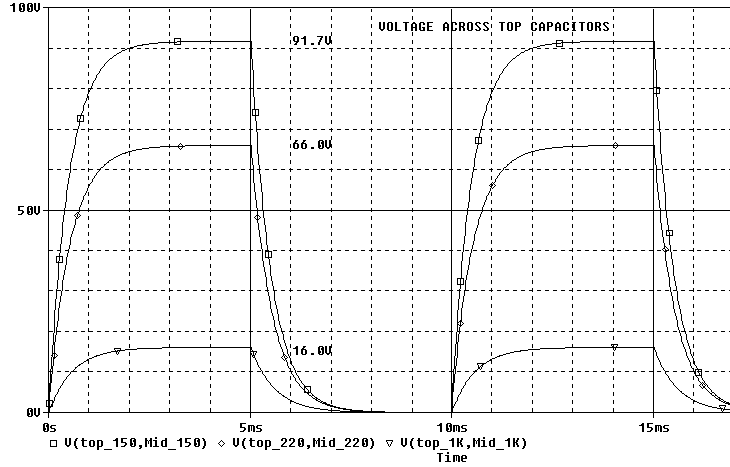
Below is what the voltage across the top capacitors look like.
Notice that the 1000 uF 15V capacitor sees 16/15 = 107% of rated voltage.

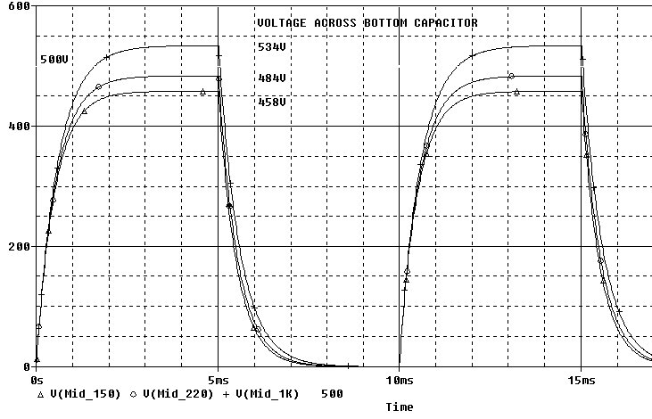
Below is what the bottom capacitors look like:
Notice that the third setup with the 1000 uF sees 534/500V = 107% of rated
voltage.

If the bleeders are not set up correctly, you'll also get imbalanced voltage stress.
Don't forget, no ungrounded metal exposed to fingers!
Use this information at your own risk. .
 ( New
2024 index page.)
 _( Old 2003 index page.)
 _( AMP Second index
page.)
 ( Fancy index page.)