Notes on Reading Schematics
First edition 02/23/01
Tube
design information
Basic
electrical training (NEETS)
Schematic Reading Help
First edition 02/23/01 Last update 02/23/01
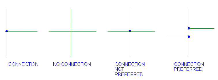
1. A dot where two wires cross means there is a connection (solder joint)
there.
A three wire connection that looks like "T" means there is a
connection there even if there is no dot. It is good practice to use a dot
on a "T" connection.
2. The standards say that two wires crossing in a + are not supposed to be
connected unless there is a dot in the middle of the +.
It is good practice to never use a + connection with a dot. Why?
The dot can disappear when the schematic is copied for the 12th time.
Caution: not everyone follows the standards.

3. Generally, inputs are supposed to be on the left, outputs on the right
and the current flow from top of the page down to the bottom of the page.
Few people follow this standard.
4. When a wire goes to a name, like B+, you can write the name of the
wire on all locations the wire appears instead of drawing lots of wires to
show this wire is hooked up. Good practice is to only do this on shared
signals like power supply wires. The purpose of this is to make the
schematic more readable.
It is good practice in a schematic to always use the same
character for a "space" in a name to avoid mistakes. Do not use
INPUT_FILTERED and INPUT-FILTERED. Stick with underlines where ever
possible to avoid confusion with "-" minus signs.
All Those Greek Letters
First edition 02/23/01 Last update 03/02/01
p means pico or 1/1,000,000,000 this is
"mm" or "uu" in some old designs for (1/1,000,000)/1,000,000
n means nano or 1/1,000,000,000
"u" or on old parts "m" means micro or 1/1,000,000
m on new designs means milli or 1/1,000
k means kilo or 1,000
M or meg means mega or 1,000,000. I prefer meg to M.
G or giga means 1,000,000,000
A 2.0 K and a 2k0 resistor are the same value and both are 2000 ohms.
A 1.0 u and a 1u0 capacitor are the same value and are 1 microfarad.
I prefer the 1u0 over 1.0u because the "." can easily get erased and
become 10u capacitor.
w (omega) is usually means 2 * PI * frequency.
j (or i) is the square root of -1 (don't sweat this, you'll go nuts)
XC is the impedance of a capacitor = 1/( jwC). Current
occurs before voltage on a capacitor.
XL is the impedance of an inductor =
jwL.
Voltage occurs before current on an inductor.
On a pure sinewave, the peak voltage is sqrt( 2) times the RMS.
Beware, the average RMS and true RMS are only the same on a pure
sinewave. True RMS is always higher than average RMS.
RMS Root Mean Squared.
Voltages on transformers in schematics are usually loaded RMS voltages.
Unloaded RMS voltages can be 1 to 50% higher than the loaded RMS voltages.
Expect the unloaded voltage to be 5% higher than the loaded RMS voltage on
fairly good transformers.
The voltages on transformers in schematics ARE NOT loaded RMS voltages
when you are using a PSPICE schematics. PSPICE transformers use the
unloaded peak voltage. PSPICE outputs also usually read out in peak
voltage, not RMS voltage. It is easy to get mixed up in PSPICE whether or
not you have peak or RMS voltages. So when you see a PSPICE output or
schematic, be very careful on whether the voltage is peak or RMS. If you
are doing relative measurements (using dB) in PSPICE, as long as you
consistently use peak or consistently use RMS in the equations, you will
get the right answer.
Those Log Beasties
First edition 03/02/01 Last update 03/02/01
LOG or log means the logarithm of a number in base 10. The inverse of LOG
is 10^x.
LN or ln means the logarithm of a number in base "e". The inverse of LN is
e^ x.
When calculating gain in dB, the impedance must stay the same for
numbers to be legal.
When calculating the ratio of two voltages we use:
20 * log( V1/ V2) V1 and V2 are the absolute value of the voltage,
leave the "-" signs off front of the number.
20 * log( -10/ 20) is not right.
20 * log( 10/ 20) is right and equals -6.020599913. We normally say -6
dB for this or 6 dB down.
20 * log( 10E-6/ 20E-6) is right. The "-" after the "E" indicates that
10E-6 is (10 * 10^-6) or 0.00001 or (10/1,000,000).
When calculating the ratio of two power we use:
10 * log( P1/ P2)
This works is because the resistance used is the same for both
measurements.
P! = V1^2 / Rload
P2 =V2^2/ Rload
P1/P2 = (V1/V2)^2
10 Log (P1/P2) = dB
10 Log (V1/V2)^2 = 10 * 2 *
log(V1/V2) = 20 Log (V1/V2) = dB
.
First version 19 Jan 01 Last change 1/26/02.
 ( New
2024 index page.)
 _( Old 2003 index page.)
 _( AMP Second index
page.)
 ( Fancy index page.)
