1. If you try to burn in a speaker with white noise, the tweeter gets way too much power and can burn out when you set the burn in power high enough to get a useful volume for the woofer. If you use Pink noise, the risk is much lower that you'll burn the tweeter out. Even with a "pinked" burn-in signal, you can always dump too much power into a tweeter by cranking the volume up too high.White noise has constant amplitude for every Hz through out a frequency range. Every octave in a frequency range has twice as many Hz in it as the octave before it. Because of this, each octave will have twice as much power in it as the octave before.2. Pink noise sounds much better if you are in earshot of the speaker(s) being burned in.
Pink Noise's amplitude rolls off at -3 dB per octave. Because of this unique roll off, every octave will have the same power in it. (-3 dB is half the power.)
Pink Noise is different than a single pole RC low pass filter which rolls off at -6 dB per octave. Pink Noise has a -3 dB/ octave roll off. This roll off is at rate proportional to 1/sqrt( frequency). A one pole (RC low pass) rolls off at rate proportional to 1/frequency.
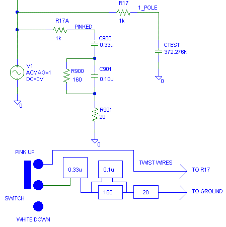
Since this circuit is used for burn-in, the "pinking" does not have to be perfect. A switch is used between the left side of "R17" and the two caps and two resistors that are gong to ground (pin 14 of the modulator.) This switch is used so that we can go back to white noise to burn-in items that can take the high frequency power in white noise. The pinking parts are soldered directly to the switch and the R17 left wire is twisted with the wire that connects the pinking parts to ground. Note: Left and right are view with the RCA connections pointing down on the PWB.
The 20 ohm is in the design for circuit
protection. If you change from pink to white with the power on the caps
will retain a charge. When you close the switch with the power off the
caps will discharge into the modulation IC. R901 (20 ohms) limits the
current into the IC when this happens and greatly lessens the chance
that the FryKleaner will be damaged. R900 and C901 are tuned up for
having R901 installed, so use R901.
"R17A" is just a reference name for the SPICE model, it isn't installed in the circuit. The added parts go across R17 in the 2004 version of the FryCleaner(tm).
X7R ceramics are OK for the capacitors
used.

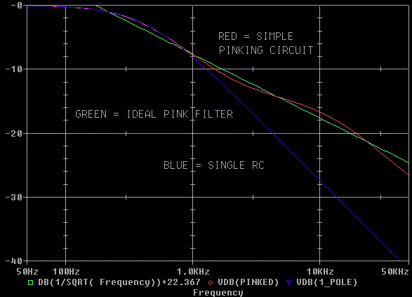
The Pinking filter responds as follows:

The "pinking" fit is pretty good for four
parts. You can see with a single RC circuit we have much more
attenuation at 20 kHz than we do with the Pinking filter.
I purposely started the roll off at 411
Hz (-3 dB) so that woofers would get an extra work out.
First edition 07/29/04. Last update: none
I don't change the update
date on individual sections for minor corrections.
I only change the date for content changes..
 ( New
2024 index page.)
 _( Old 2003 index page.)
 _( AMP Second index
page.)
 ( Fancy index page.)