Parafeed Fun
First Web Edition 1 Jan 07, Last update 31 Jan 07
Caution: This
web page deals with high voltages.
Contact with these voltages can cause injury and/
or death
both to you and what you land on after being
shocked.
Unplug it, discharge it, measure it
(DC and AC) before touching it.
This is the first web page where
I'm not supporting Netscape 4.7, wish me luck.
Related pages:
There
have been a few Parafeed spreadsheets popping up on the Internet and
with some prodding from Mikey, I decide to make one of my own over
Christmas. A nice man from NY helped by introducing me to the
complex functions in Excel. The last time I did calculations like this,
I did the calculations the hard way and did the complex math long hand.
The complex functions in Excel make life much easier. Long hand math is
for homework assignments in college.
The first step was to use Pspice to get a few "Error Free" plots
to check the spread sheet against. This will also let me know what plots
I want to put in the spread sheet.
The plots start at 1 Hz. This is useful for seeing
trends below 20 Hz, but what we normally care about is what is happening
at 20 Hz and higher.
The plots stop at 1000 Hz. The model we are using isn't valid above 1000
Hz because it does not include parasitic capacitances and leakage
inductance.
The trick will be to keep our eye on the
"big picture." We want to:
- Optimize
the power supply rejection, more specifically, power supply
rejection divided by the output voltage
- Optimize
the output impedance of the amp, i.e. don't throw away the damping
factor.
- Optimize
the load line on the tube and
- Optimize
the frequency response of the output over the entire audio range
- WITHOUT
messing anything else up and WITH having enough cash left over at
then end of the day to enjoy a glass of original Dr Pepper from Dublin Dr. Pepper.
Part 1
In this section,
we'll look at a simple model and vary the plate choke, Parafeed
capacitor and transformer primary inductance one at a time to see
what they do.
Part 2
In
this section, we'll look at adding a few losses to the
circuit.
Part 3
In
this section, we'll add DrP (Damped Resonance Parafeed.)
Part 4
In
this section, I'll introduce an Excel spread sheet to run
these plots.
Part 1:
The Simple Model
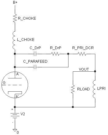
Here is a simplified model of a Parafeed circuit. The DCRs of
the plate choke and transformer are omitted and the impedance of the B+
is set to zero. Because the losses in the iron and copper are not
included in the model, when we see resonances, they will be are larger
than in real life.

Here is
a basic frequency sweep with a huge 40,000 Henry plate choke. This is
equivalent to a CCS feeding the tube instead of a plate choke.
- The top trace is the output of the
amplifier in dB.
- Generally the flatter the
better.
- Gentle slopes as we go below
20 Hz towards 1 Hz are usually better than steep slopes
down.
- Note that the difference
between a -3 dB point at 20 Hz and 22 Hz is probably not audible.
- Remember, keep an eye on
the big picture.
- The bottom trace
[(V(Plate)/I(V1))] is the plate load impedance as seen by the tube.
- The higher is better if the phase angle is at zero degrees.
- If the phase angle is not
zero, higher impedance is still better, but 5K at zero degrees is
usually better than about 6K at 45 degrees.
- The middle traces are the phase
angle of load impedance seen by the tube (green) [P(-V(Plate)/I(V1))]
and the phase angle of the voltage at the output (red)
[P(V(Primary))].

Now lets
drop the plate choke down to an affordable 40H. My normal rule of thumb
for a plate choke is it should be 8H for every kohm of load or larger.
So with a 5K load, the plate choke should be about 40H or more.
Other people use 10H per kohm of load as a rule of thumb. The difference
between 40 and 50H isn't that big. We normally don't care about the
phase shift at 20 Hz to the speaker (red trace in middle plot), but it
is included in this plot anyway.

The
running of plots one at a time makes it difficult to see what is
changing. So what I'll do next is sweep one parameter at a time (plate
choke, Parafeed cap and primary inductance) so we can see what each
parameter does.
Part 1.1
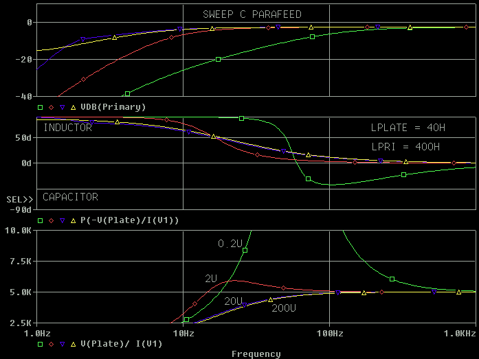
Let's see what the Parafeed cap does at 0.2 uF, 2 uF, 20 uF and 200
uF.
Lets run
plots with the Parafeed cap set to 0.2 uF, 2 uF, 20 uF and 200 uF.
For clarity, I deleted the phase at the load (the speaker). We care more
about the phase angle of the plate load seen by the tube than the low
frequency phase at the speaker. We can see more capacitance leads to a
lower - 3 dB frequency (good), a flatter phase angle on the load line
(good) but a lower impedance load line (not so good if it occurs in the
audio range.)
--- There are two other things we care
about in an audio amp. ---
There
are at least two other things we care about in an audio amp. The top two
things that come to mind are the power supply ripple rejection and
output impedance (damping factor).
- The power supply rejection is run
with the load attached to the amplifier.
- -40 dB is better than -30 dB
for the power supply rejection. However, I doubt anyone could hear
the difference between -40 dB and -37 dB at low frequencies. The top set of curves is the power supply
rejection in dB, more
negative (lower) is better.
- Note: Yes I know rejection
should be specified as a positive number, but the plots are
easier as a positive number.
- -40 dB means 1V of ripple
on B+ is reduced to 0.01V a the primary of the transformer.
- There is a question to be
resolved: Display actual power supply ripple rejection or
display ripple rejection divided by small signal output response.
This isn't signal to noise because noise involves more sources
than just the power supply, but it is similar. The advantage
of this is it is harder to fool ourselves that we've improved the
PSRR with out hurting anything else.
- The output impedance of the
amplifier is usually measured with the load removed from the output of
the amplifier.
- This will remove any damping
the speaker provides for the amp; however, we want the amp to damp
the speaker, not the other way around.
- The
bottom trace is the impedance at the output of the amp (lower is better) with the
reflected transformer load impedance removed from the
equation with different Parafeed capacitors.
- The peaks in real life won't
be that high because of losses in the iron, but the trend will be
the same.
- Lower Parafeed capacitor
values leads to higher output impedances (lower damping factors.)
For both curves: Lower is better, flat
is better.
First lets look at the results displayed as Power Supply Rejection
and Output impedance.

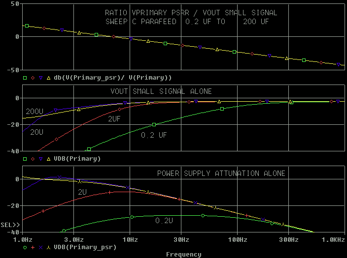
Now lets decide how we want to display rejection of B+ ripple, PSRR. Lets
examine the plot below to see what we learn.
- The bottom plot is PSRR displayed
as how much ripple from B+ actually makes it to the output.
- 0.2 uF looks impressive
compared to all the other values. However, remember: There Ain't
No Such Thing As a Free Lunch. (TANSTAAFL) [1]
- The middle trace is how much
voltage swing from the tube actually makes it to the output.
- Notice that 0.2 uF rolls the
output off at a fairly high frequency. This is one "Bills" we pay
for a "good PSRR lunch". The question is did we get what we paid
for?
- The top trace is the bottom trace
divided by the middle trace.
- This normalizes the voltage on
the output from the power supply to the voltage on the output from
the tube. This allows us to make a better comparison of what the
changes do.
- Looking at the top plot, we
see that changing the Parafeed capacitor value doesn't affect the
PSRR when it is normalized to the output response.
- Digging deeper, this means for
dB we gain in B+ ripple rejection we lose a dB in audio output.
- In other words for
every dB in rejection we get we loose a dB of music.
- [1] In engineering, we also say There Ain't No Such Thing As a Free
Variable (TANSTAAFV), but some are pretty cheap!
In
general,
- Zout (damping) is better with
large Parafeed capacitors.
- -3 dB at the output is better with
large Parafeed capacitors
- The load line (impedance seen by
the tube) is best (to my eyes) with a medium Parafeed capacitor. A
small Parafeed capacitor gives the highest load impedance, but the
phase angle [ P(-V(plate)/I(V2) ]is not resistive so the load line
becomes elliptical.
- A small Parafeed cap gives better
power supply rejection at low frequencies, BUT, this rejection is at
the expense of a higher - 3 dB point and a worst damping factor. I'd
stick with medium to large Parafeed capacitors.
Hint: The less you work a capacitor (change the voltage across it),
the better it will perform.
Overall,
I'd start a design with a moderate Parafeed cap: 8 uF / 1K of plate
resistance (1K = 8 uF, 2k = 4 uF). More capacitance will give better
damping. A lower value will roll off the -3 dB point so as to not drive
the Parafeed transformer as hard if saturation is a problem. If I wanted
to raise the -3 dB point (say from 20 Hz to 40 Hz), my preference would
be to use the large Parafeed capacitor for good damping and roll the -3
dB point off in the drive to the output stage .
Part 1.2
Let's see what the plate choke does at 4H, 40H and 400H.
Let's
examine
what happens with the plate choke at 4H, 40H and 400H with the Parafeed
cap (Cpara) set to 2 uF and then to 20 uF.
- On the top plot (VdB(Primary)) we
want to see a low - 3dB frequency without peaking.
- The bottom trace
[(V(Plate)/I(V1))] is the plate load impedance as seen by the tube. We
want this to dip down at as low a frequency as possible.
- The middle plot is the phase angle
of the the plate load impedance. We'd like this to be zero degrees to
as low a frequency as possible.

.

Here's
the power supply rejection (top) output impedance (bottom) with the
plate choke at 4H, 40H and 400H.
For both curves: Lower is better, flat is better

.

Here's
one where the PSRR isn't normalized. When it is normalized, it is easy
to see that at 4H, the power supply noise is higher than the music below
about 80 Hz. When it isn't normalized to the output response, we
completely miss this wonderful discovery.

In general,
- Zout (damping) can be better with
smaller plate chokes (4H).
- -3 dB is better with large plate
chokes (400H)
- The load line (impedance seen by
the tube) is best with a large plate chokes (400H).
- The Power Supply rejection is
greatly influenced by the plate choke and more inductance is better.
The improvement in damping from smaller plate chokes can be
easily lost to the higher -3 dB points and to lower output power due to
elliptical low impedance load lines and the loss in "real" B+ noise
rejection. The other issue with using a small plate choke to improve the
damping is the damping runs through B+ and not directly to ground. For
the plate choke, I recommend a moderate (8 H/K of primary reflected load
impedance) to high values (400H or CCS drive.)
Part
1.3
Let's examine
what happens with the primary inductance of the transformer at 4H, 40H
and 400H
Let's
examine what happens with the primary inductance of the transformer at
4H, 40H and 400H with the Parafeed cap (Cpara) set to 2 uF and then to
20 uF.
- On the top plot (VdB(Primary)) we
want to see a low - 3dB frequency without significant peaking.
- The bottom trace
[(V(Plate)/I(V1))] is the plate load impedance as seen by the tube.
- We want this to dip down at as
low a frequency as possible.
- Upward peaks are acceptable if
the phase angle stays close to zero.
- The middle plot is the phase angle
of the the plate load impedance. We'd like this to be zero degrees to
as low a frequency as possible.

.

Now for the PSRR and output impedance.

.

I've been told that most good Parafeed Transformers will run 50H of
primary inductance per kohm of rated primary impedance. This means a 5K
primary should run around 250H.
- Large Parafeed Primary inductances
are good in just about all ways we've looked at.
- The correct way to get large
primary inductances is through careful manufacturing and good
materials
- Adding lots of primary
turns on the same core to get a large primary inductance adds
insertion loss (DCR) and leakage inductance (which makes the upper
-3 dB point worse.)
- >40H per kohm of reflected
load is a good starting point for power amps.
- The Parafeed Primary inductance
does not have any useful effect on the B+ ripple rejection.
- A small primary inductance
will attenuate the B+ ripple, but for every dB it attenuates the
B+, it also attenuate the audio.
- A low primary inductance improves
the output impedance of the amp, at the expense of a harder load line
to drive (better damping for higher distortion.)
- There may be some argument
that since the output impedance of the amp is inductive, not
resistive, it doesn't help the damping as much as it should.
Part 1.4
Summary of what we learned with the simple model
- Plate Choke
- Below 1 kHz, you can't
make the plate choke too large. Economics of weight and cost
will limit the size of the plate choke.
- The plate choke is the
only good place to get more power supply ripple rejection with
a given output tube.
- 10H per kohm of reflected
load is a good starting point for power amps.
- 40H per kohm of plate
resistance is a good starting point for driver stages and
preamps.
- Remembering TANSTAAFV
- As the plate choke
gets larger, the DCR will usually increase leading to a
higher B+
- As the plate choke
gets larger, the capacitance CAN increase which will hurt
the performance above 1 kHz
- As the plate choke
gets larger, it is more likely to couple to other parts.
- Parafeed Capacitor
- A small Parafeed capacitor
can be used to raise the lower -3 dB point to a higher
frequency.
- Why raise the -3 dB
point? Raising the -3 dB point helps keep subsonics from
robbing available output power (saturating) of the
Parafeed transformer.
- If you want to limit the
-3 dB point, I recommend limiting it in the driver stage,
not with the Parafeed capacitor.
- A small Parafeed capacitor
can reduce the coupling of B+ noise, but this has a high
performance cost in that it worsens the damping factor and
increases the -3 dB frequency.
- For every dB of B+ noise
you reject with a small Parafeed cap, you lose 1 dB of
signal.
- A small Parafeed capacitor
hurts the damping factor. A large Parafeed capacitor helps the
damping factor.
- The load line is best with
a moderate (tuned) Parafeed capacitor.
- Starting from scratch, I'd
pick the Parafeed capacitor for a flat damping factor above 20
to 40 Hz or so.
- To set the Parafeed
capacitor equal to the plate resistance at 20 Hz (the
limiting factor for damping factor), use a capacitor that
is 8 uF / 1K of plate resistance (1K = 8 uF, 2k = 4 uF).
I'd use this rule for power amps and preamps. I haven't
decided if I'd use a smaller cap in a driver stage or not.
- Start with a cheap
capacitor and voice your amp's bass, then buy a good film
and foil capacitor (oil optional)
- Don't be afraid to
experiment with the Parafeed capacitor value.
- Primary Inductance
- Higher is better in most cases.
- A smaller value used as a grid choke
in a driver stage has the advantage of recovering faster
when the grid of the output tube is driven positive.
- A smaller value can be tuned for
better damping, but at the expense of changes in the load
line and in the lower - 3 dB frequency response.
- If using a smaller Primary
inductance, you'll definitely want to play with tuning the
Parafeed capacitor.
- >40H per kohm of RATED reflected load
is a good starting point for power amps.
- You usually don't have much say in
this parameter except to order premium core materials.
Part
2
Let's
add a few losses to the simple model
Lets add the DCR (DC resistance) of the choke and the DCR of the
transformer to the model. These parasitics are easy to measure,
calculate and understand. The core loss isn't easy to measure and
most manufacturer's won't give it to you.
- DCR of the choke is fairly
straight forward. It adds a voltage drop from the DC bias of
the tube.
- The DCR of the transformer
adds insertion loss to the transformer.
- This means if we put
one watt in the input, we get less than one watt on the
output.
- There are several ways
transformer manufactures deal with the losses from the
DCR.
- The turns are set
to the ideal turns ratio. Both the reflected primary
impedance and the output voltage will be off.
- The turns are
compensated so the loaded output voltage is correct
(this is usually done on power transformers.)
- The turns are
compensated so the loaded primary impedance is correct
(some audio transformers.)
- A combination of
the above.
- I'm using an impedance
compensated model for the transformer (the primary
impedance is correct.)

Sweeping the plate choke at 4H, 40H and 400H, we get an output
response that looks like the following. It is kind of hard to tell
the difference between the two except that the output is about a
dB lower.

Subtracting the two outputs gives us a magnified view of what is
changing.
The top plot shows that the DCR of the plate choke adds a bit more
power supply rejection when the plate choke is small (4H).
The bottom plot shows the DCR of the transformer adds 1 dB of loss
at 1 kHz. The DCR of the choke adds some voltage gain at subsonic
frequencies.

The effects of the DCR on the output impedance can be see in the
following plot. At 1 kHz, the DCR of the transformer makes the
damping factor 1.26 times worse.

The output impedance of the amplifier is dominated by the plate
resistance of the tube followed by the resistance of the
transformer windings. If you want better damping in a SET or
Parafeed amp with a given tube, you have to give up some output
power and use a higher primary impedance on the transformer. A 10K
primary should have two times better damping than a 5K and a 5K
should be twice as good as a 2.5K. Remember TANSTAAFL? To get the
better damping we give up something. If 2.5K is the resistance
needed for maximum power out, the 5K and 10K will give
progressively lower output power for the same tube and bias point.
Part
3
DrP,
Damped Resonance Parafeed
It's more than an excellent soft drink.
(Plots
and long diatribe to be added later)
With good iron in a Parafeed power amp, DrP doesn't help too much.
You can some times use it to tweak a bit more low frequency power
out.
If we use budget iron, Damped Resonance Parafeed adds some
additional parameters we can tweak to trade off power handling vs
damping vs -3dB points.
In a driver stage or preamp, DrP can greatly reduce the low
frequency resonance of the unloaded Parafeed tank without having
to add a resistor across the grid choke or Parafeed transformer to
ground. This is good because it gets us a little more voltage gain
out of the circuit and greatly reduced the loading on the tube
(which makes the tube sound better in my book.)
Because
of the DrP resistor in series with the DrP capacitor, the
Parafeed capacitor shorts out the "sound" of the DrP cap at
almost all frequencies. This means the DrP cap can be a
slightly lower grade than the Parafeed capacitor. I happen to
like metal foil capacitors. DrP means I could use a metal foil
(film and foil) capacitor for the Parafeed capacitor and then
use a metalized cap for the DrP cap.
Click
on
this link for technical discussions on Transformer / LC Tank
Damping
Part 4
A Spread Sheet to Play With
To use this spread sheet, you'll
need to have your EXCEL install disk in hand and do the following:
In Excel, Click on
Tools
Add-ins
Analysis ToolPak
[not the Analysis ToolPak - VBA]
Put your Excel install disk
in the CD drive and follow the rest of the instructions.
Click here to get the Excel File: Parafeed Circuit Spread Sheet
The Excel spread sheet models this
circuit from about 1 Hz to 1 kHz.
The data section of spread sheet looks something like this:
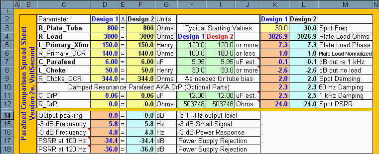
The spread sheet will model two designs at once so you can
compare them. INPUTS
- All inputs are in cells with a YELLOW back ground.
- The Rplate of the tube and Rload are the easy
numbers to pick. If you don't know what the numbers are, just
used the suggested "Typical Starting Values"
- If
you don't want to use DrP, just set the C_DrP = 1% of the actual
Parafeed capacitor and the R_DrP= 0.
- To
make this a CCS fed Parafeed, Set the R_Choke_DCR to 1,000,000
Outputs
The normal things we care about are
listed in a table format
- The Output Peaking is the
highest peak from 1 Hz to 1 kHz with respect to the 1 kHz output
level to the speaker.
- The -3 dB Small signal
frequency is the calculated -3 dB low level response
assuming the inductance of all the magnetics does not change with
drive or frequency.
- The - 3 dB power response is
where the load on the tube drops to 70% of the 1 kHz load. On
preamps and grid choke designs, this number will have no meaning.
On a tube with a load impedance set to maximum power output, this
number is the frequency where the distortion starts to rapidly
climb.
- PSRR at 100 Hz and 120 Hz is
how much the Parafeed design attenuates the B+ ripple at 100 Hz
and 120 Hz.
Spot Frequency Check
Cell K3 (30 Hz) lets you input a
frequency for a detailed analysis. You can enter any frequency you
want between 1 Hz and above 1 kHz.
One thing that is missing
is an analysis of the transformer saturation limited allowed output
power vs frequency. I'm not sure this is a big deal to not have it.
- I'm not sure if we can get consistent data from
the transformer manufacturer's that is taken at the same level
of peak distortion, input loading, output loading etc.
- I'm not sure if anyone other the Paul Joppa could
use that curve without messing up all the other parameters.
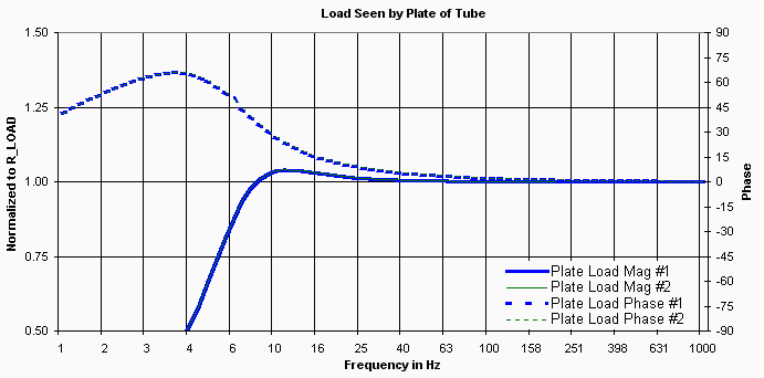
The "normalized" load impedance seen by the tube vs
frequency plot looks like the following.
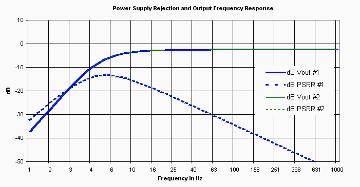
The small signal frequency response and power supply rejection is
given in a plot that looks like the following. For dB out, flat and
a low - 3dB is best. For PSRR, in this plot more negative is better
(-50 is better than -40). If you look close, you'll see the 1 kHz
Vout is not 0 dB. This is because the plot shows the effects of
loading on the tube.
Part 4.1
Lets Examine a Driver Stage.
- CCS fed plate
- Set
R_Choke_DCR to 990k
- 1000
times R_plate is also a good way to change to a CCS drive
- .33 uF Parafeed cap
- 750H 900 grid choke with no parallel resistor [
Note: Set R_load to 990K or 1 meg ]
- 7000 ohm Rplate
We see that the output peaking (Design 1) is 13.4 dB
and if we increase the capacitance by adding the DrP cap with no
series resistance, the peaking is 11.2 dB. This is a hint that just
adding more capacitance won't kill the peaking easily.

Lets add the estimated value for R DrP and see that the peaking drops
from 11.2 dB down to 5.32 dB.

Just for kicks, we'll use the Excel Goal seek function to try to drive
the peaking down.

Goal Seek function is found under
TOOLS
Goal SEEK
The trick to using goal seek is not to get greedy
all at once. Don't go for zero on peaking. Go for a little smaller
than the existing peaking. If it doesn't work, try a different goal
and it may work. In this case, the goal seek couldn't find a better
value than the estimated value.
With a 0.33 uF DrP, the output response's improvement can be seen in
the following plot.  DrP works better with the DrP cap set to 2 to 3
times the Parafeed capacitor. Using the suggested DrP resistor, 2X cap
has 3.19 dB peaking where 1X had 5.32 dB peaking. After running the
goal seek optimization, the 2X gets 0.01 dB better. Not that big of a
deal. This also shows that the DrP resistor isn't very sensitive to
its value. We changed it 10% and got almost no change.

Lets check a 1 uF DrP. Going from 2X to 3X buys us 1 dB less peaking.
For 1 dB I'd just use the 2X value.
 The historical way to kill the subsonic peaking in
a driver is to put a resistor across the grid choke. This kills the
peaking, but it makes the driver tube work harder. Lets use Goal seek
to pick a damping resistor across the grid choke and compare it to a
2X DrP damping cap. Remember to use small steps when tweaking in the
peaking by changing part values with goal seek.
To get "0 dB" peaking we need to put a 36K resistor across the grid
choke.
 At 1 kHz, the grid resistor costs us 1.5 dB
in gain over adding the DrP cap.

Now for the interesting plot.
- The load the driver needs to drive is about
501K at 1 kHz using DrP
- The load the driver needs to drive is about
34K at 1 kHz using the damping resistor across the grid choke.
- At 40 Hz, DrP presents a 166K load to the
tube and the resistor across the grid choke presents a 34K load.
I'd much rather have the 166K load on the tube
than the 34K load on the driver tube.
 Now to be fair to the Resistor across the grid
choke damping method. Lets increase the resistor across the grid choke
until the load at 40 Hz is 166K. This requires using a 1.09 megohm
resistor across the grid choke. The peaking is now 13.6 dB with the
resistor across the grid choke instead of 3.2 dB with the 2X DrP
configuration.

Like I said, DrP. . . it's
more than an excellent soft drink.
Here's the before and after schematic. Note: R4 and R8 aren't real
resistors in the circuit.

Here's the DrP plots. The output peaking is slightly different than
the Excel spread sheet mostly because the Pspice plot uses fine
frequency steps and the Excel plot uses course frequency steps.

Part
4.1.1
Is
This Gain Peaking a Problem?.
Lets not lose track of the ball:
- Take all measurements with a grain of salt.
We are talking tubes here. If measurements meant something
actually sounded better, we'd be listening to Solid State.
- Measurements are good for helping us make decisions
instead of guesses. Measurements won't tell us how it
sounds, but they can help us understand what we need to change to
improve the sound. This is as long as we don't mess anything
else up in the process and we're smart enough to make the
"right" measurements.
Thoughts on 1-20 Hz gain peaking
issues:
- Because the “5 Hz” gain
peaking can be excited by B+ and grid conduction, rolling off the
gain of previous stages does not completely remove the risk of
having problems.
- 1-20 Hz is a problem area with
LPs. Subsonics from a record can aggravate low frequency gain
peaking.
- 1-20 Hz could be a problem
with bias recovery from repetitive clipping (either at the drive
tube or forward biasing the grid of a tube on the output of the
Parafeed stage.) Asymmetrical clipping is usually worse than
symmetrical clipping.
- 1-20 Hz can be a problem with
115V line modulation. I've seen a 3 Hz B+ ripple in my equipment I
can't explain. Line dips and peaks could cause large excursions in
the bias point. Plug a 500W lamp in to the same outlet as the amp
to check for problems when the lamp is turned on and off.
- 1-20 Hz could be a problem
with motor boating between tube stages that share a power
transformer.
- IF there are more than one
gain stage in a system, make sure that if there is peaking,
that the peaking does not occur at the same frequency. Three 15 dB
peaks at 5 Hz gives a total system peak of 45 dB. With multiple
stages and amps, either split the frequencies where the peaks
occur an octave apart or damp the peaking some how.
Play safe and
have fun out there.
If you have questions or comments,
contact me through Asylum Mail.
First version 01 Jan 07, Last update 31 Jan 07 .


 At 1 kHz, the grid resistor costs us 1.5 dB
in gain over adding the DrP cap.


 ( New
2024 index page.)
 _( Old 2003 index page.)
 _( AMP Second index
page.)
 ( Fancy index page.)