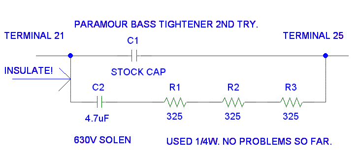
The damping capacitor needs to be the same or slightly larger than the parafeed capacitor. This series resistor will have to be tuned. The resistor changes the Q of the parafeed tank near resonance.
Starting points for the resistor tuning:
1. R = sqrt(
L_parafeed in parallel with L_output_transformer / C_parafeed) (round up
in value)
Note: C_parafeed = C1 shown below
2. R = 1/(2 * PI * F_-3db * C1)
This how Lossy Parafeed is installed:

The Paramour 2A3 grid coupling capacitor is 0.33 uF with 133 kiloohm to signal ground. These pictures were taken with the Sino 2A3s. All pictures are with the scope is at 5 msec/ div. The top trace is the plate of the 2A3 at 50V /div. The top of the screen is adjusted to be at 450V. The bottom trace is the output at 2V/ div.
Most of these images consist of two, usually three, separate images pasted together to make one complete picture. I must admit that I am not happy with these pictures. When I first implemented "lossy parafeed" in the Paramour, I has some really nasty looking waveforms that where calmed down with the "lossy parafeed." I can't seem to repeat what I was doing to make those nasty waveshapes. I had intended to increase the resistor in series with the 4.7 uF to show differences in the improvements you can get with "lossy parafeed," but because I can't get that nasty waveshape back, there is no point in the exercise.
These three pictures are with no load and with stock Paramour magnetics.
Stock Parafeed capacitor. (No load, Top Trace
Plate, Bottom Trace 8 ohm output)

Below is the 8 ohm output of the Paramour with an
additional 4.7 uF capacitor across the existing parafeed
capacitors. Notice that there is a dip in the plate voltage before
it flat lines and the sharp edge in the output waveform. (No load)

Below is the 8 ohm output of the Paramour with
lossy Parafeed of 4.7 uF and 975 ohms. Notice that the plate waveform
and the output wave form look smoother as they reach "flat line." (No
load)
Look at the waveform three grids in from the left to see what I am
talking about.

Now lets look at the same three pictures with a 8.45 ohm load on the 8 ohm output with stock magnetics.
Stock Parafeed capacitor. (8.45 ohm load, Top Trace
Plate, Bottom Trace 8 ohm output.)

Below is the 8 ohm output of the Paramour with an
additional 4.7 uF capacitor across the existing parafeed
capacitors. Notice that the output (lower trace) does not
undershoot (good). Notice that the output has "more area under the
curve" with nearly twice the Parafeed capacitance as the stock
Paramour (good). Notice that the plate is pulled lower than with the
stock capacitor. This means the plate is delivering more current (bad
and good.) (8.45 ohm load)

Below is the 8 ohm output of the Paramour with
lossy Parafeed of 4.7 uF and 975 ohms. Notice that the plate waveform
and the output wave form look smoother (good.) Notice that the plate is
slightly higher indicating it is delivering less current for nearly the
same output (good.) (8.45 ohm load)

Now lets look at the same three pictures driving a Radio Shack Minimus-7 on the 8 ohm output with stock magnetics
Stock Parafeed capacitor. (Minimus-7 load)

Below is the 8 ohm output of the Paramour with an
additional 4.7 uF capacitor across the existing parafeed
capacitors. Notice that the output (lower trace) does not
undershoot (good). The plate and output shows a little more ringing
(bad/possibly good.) Notice that the output has "more area under the
curve" with nearly twice the Parafeed capacitance as the stock
Paramour (good). Notice that the plate is pulled lower than with the
stock capacitor. This means the plate is delivering more current (bad
and good.) (Minimus-7 load)

Below is the 8 ohm output of the Paramour with
lossy Parafeed of 4.7 uF and 975 ohms. Notice that the plate waveform
and the output wave form look a tiny bit smoother (good.) Notice that
the plate is slightly higher indicating it is delivering less current
(good.) (Minimus-7 load)

I've received mixed feedback from those who have tried Dr P in their SETs. Some heard nothing. Some liked it. Some didn't like it.
A. If you don't like it, check the tuning. Every manufacture's output transformer and plate choke will have a different tuning. If you still don't like it, don't use it. THIS IS DIY. You solder on it until you are happy with it. When you are happy with it, you sit back with a cool drink and just enjoy it. What I've seen is those with really good output iron and high inductance plate chokes don't get as much benefit. (For now, good is the XL from the inductance of the iron is greater than the reflected load impedance at <= 20 Hz.)
XL = 2 * PI * Freq * inductance.
B. If you like it. Great! Go play some tunes.
C. If you heard nothing, Try it with a different speaker before you rip it out. Some speakers absolutely don't need the benefits from any low frequency damping in the Parafeed network. If you still don't hear anything, take the parts out and go play some tunes.
 ( New
2024 index page.)
 _( Old 2003 index page.)
 _( AMP Second index
page.)
 ( Fancy index page.)