S5 Electronics K-12M Tube Amp
Remember to completely unplug the unit and
let the capacitors discharge before you solder on it.
Caution: There is no safety
bleeder in the stock amp.
So you will want to build an insulated clip-on
discharge resistor to discharge the B+ caps.
Notice:
1. This project deals with lethal 115V
line voltage and higher voltages. You yourself must assume the
responsibility for your own safety and for those who come near your
work.
2. If you modify the kit, you void your warranty
and neither S5 nor I will take responsibility for your changes to the
amp.
3. This is an open notebook for sharing with my
friends. Use any information enclosed here at your own risk.
4. Don't contact me if the kit or mods don't work.
Learn to fix it.
5. This is based on the 2001 version of the kit.
If the kit changes, the mods may not work in your version.
I felt the need to build something. My big project
isn't going very fast (I'm avoiding the metal work.) I heard the K-12M
Tube Amp at the April Cactus Tube Dudes and thought I would play with it a
bit. I ended up buying the version with the tube cage. The metal work was
already done!
S5
Electronics Collects the Parts for the KIT and does the warranty work.
Arizona
Hi Fi is the place I bought mine.
AudioExpress
Review
of K-12M amp.
This 11MS8 amplifier was designed by George Fathauer
and has the following advertised specifications:
Input
Impedance
=
100k ohms
Rated
load
= 8 Watts into 8 ohms per channel.
Minimum Input for full output = 400 mV
Frequency
Response
=
20 to 20,000 Hz
THD at 1
Watt
<1%
Performance Measurements I made:
On the stock amp I measured an output
impedance at 30 Hz of 4.5 ohms, 300 Hz of 5.1 ohms and at 3 kHz of 5.1
ohms.
At 3 kHz, I noticed that clipping just started at
17V peak to peak into 8.45 ohms (resistive.) This is 9 watts peak
output. 4.5W RMS.
The documentation for the kit is adequate, but minimal.
The web site instructions are a bit easier to read. However, I didn't
exactly follow the instructions to the letter.
Before I started the assembly, I clear
coated the bottom of the chassis with about 6 coats of clear spray paint
and very lightly wet sanded it in water with 600 grit after every coat
but the last coat so that it would look nicer. I also painted the black
top sandstone brown. I don't really like the sandstone brown, but I like
it slightly better than the stock black.
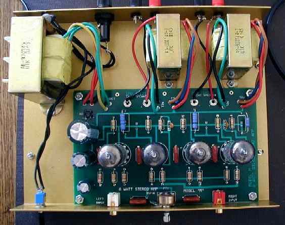
I ended up placing my output transformers
in the wrong way (as shown below) because I didn't have a picture to
look at. This ended up being a good thing because it made the board
easier to remove to do modification to it.
I checked the "polarity" of the 115V line
transformer primary with a signal generator and hooked it up so that
the 115V lead that gave the lowest chassis voltage went to 115V hot at
the power switch.
I wired the 115V differently than the kit
instructions. I wired 115V hot to the fuse first and ran a wire to the
power switch. The spare transformer lead was hard wired to the 115V
cold. I soldered the 115V cold connection and put a wire nut over it.
The wide plug is 115V cold, ohm it out to find out which wire it is.
I've been zapped by equipment with the switch in the cold so I wanted
both the switch and fuse in the hot lead.
Note: The right most tube is tube 1.
Ohm readings made with unit unplugged, caps discharged,
tubes removed and volume pot all the way clockwise:
| Measurement point |
Tube 1 and 3 |
Tube 2 and 4 |
Black lead to |
| 1 |
Open |
Open |
Speaker Black |
| 2 |
86K |
Open |
Speaker Black |
| 3 |
1.46K |
47K |
Speaker Black |
| 4 |
<1 ohm |
<1 ohm |
Speaker Black |
| 5 |
<1 ohm |
<1 ohm |
Speaker Black |
| 6 |
Open |
Open |
Speaker Black |
| 7 |
Open |
Open |
Speaker Black |
| 8 |
298 |
298 |
Speaker Black |
| 9 |
470K |
470K |
Speaker Black |
|
|
|
|
| Test Change |
Tube 1 and 3 |
Tube 2 and 4 |
Red lead to |
| 1 |
153K |
50K |
+ of diode bridge |
| 6 |
75 ohm |
85 ohm |
+ of diode bridge |
| 7 |
468 ohm |
468 ohm |
+ of diode bridge |
|
|
|
|
The following should measure less than 1 ohm to
Speaker Black:
Case of power transformer
Case of each output transformer
Chassis of amp.
Speaker Red
Some Voltages. Be careful when you test the voltages.
Clip the ground of the DVM to speaker black and don't be touching
anything metal with your body when you probe around. Getting across the
B+ or the line voltage could be the last thing you do! Forever!
R8, R17 26V
R1, R9 1.29V
R3, R13 65V
R4, R21 197V one side, 132V the
other side.
Initial power up:
My kit oscillated at 100 kHz at first power
up so I went to the web site and saw a note about a ground lug on the
volume pot. Sure enough, there was no continuity from the speaker black
terminal to the chassis because of the paint. I put an internal tooth
lock washer between the ground lug and chassis and the oscillation
stopped. After that, I put internal tooth lock washers under the both
the nut and screw on each of the transformer mounts that face the
circuit board.
Now I went to listen. The sound was good for a
$225 tube amp. There was some hum and buzz that I found annoying with
my 100 dB/W speakers so I went out to try to fix that.
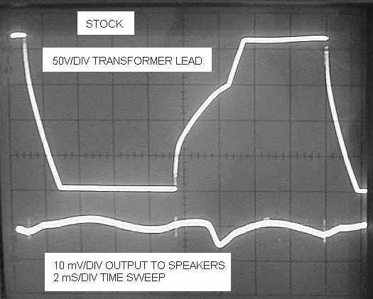
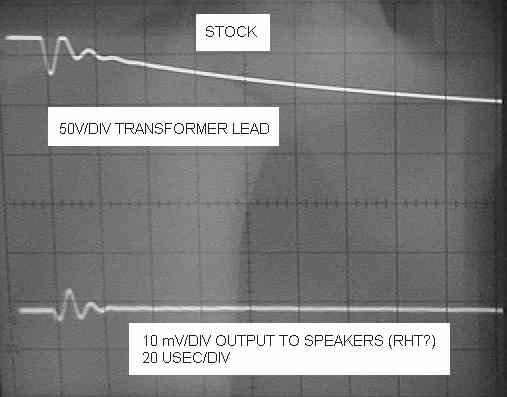
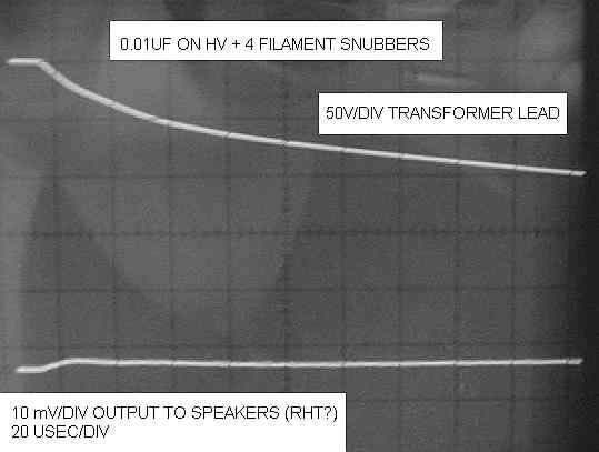
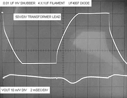
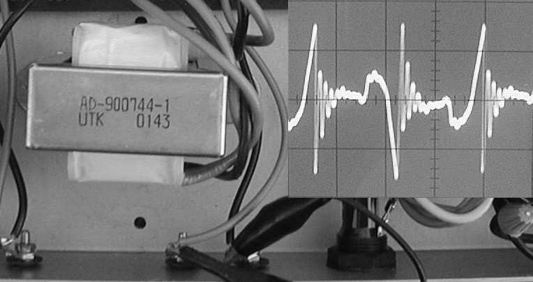
Rectifier Noise
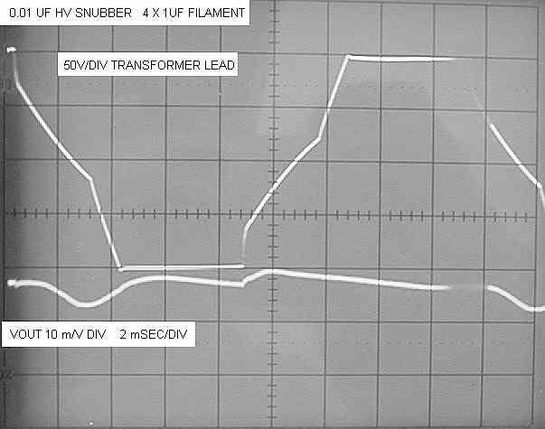
The stock amp has about 10 mV pp ripple with little
diode recovery spikes on the output. You can see the spikes every time
the top trace stops being flat and changes direction. Because the output
noise has spikes and sharp points, it will be very broad band noise. The
spikes show up as tweeter noise and the jagged edges as midrange noise.
The output noise also has "wiggles" in it that do not show up in the
photo. This usually is a "hissy" type of noise.
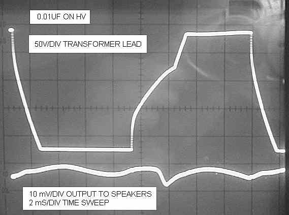
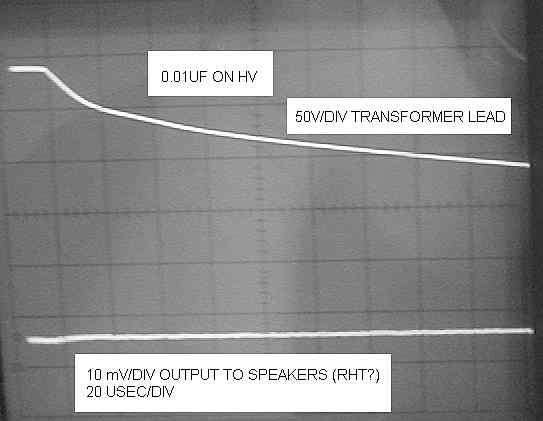
With a 0.01 uF 2 kV Radio Shack ceramic across the
HV transformer leads, the narrow spike on the output goes away, but the
low frequency stuff stays.
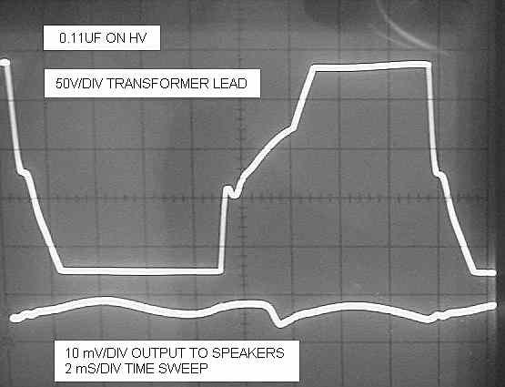
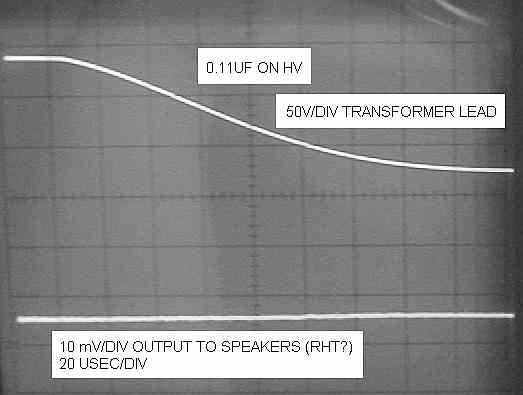
With a 0.1 uF 400V film across the 0.01 uF. The
output looks like it has a little less low frequency noise, but overall
things look a little worse so I left the 0.01 uF in. I'll go back and
tweak it up better another day.
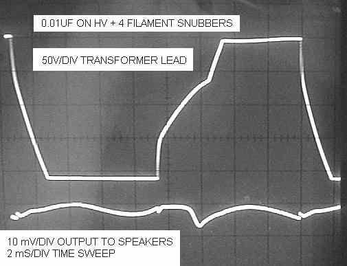
It is not apparent in the scope pictures, but the
output trace is still "fuzzy" with high frequency noise. So I added four
1 uF caps as filament snubbers. This made the trace much thinner, but I
got a little bump back in the output noise from the diode recovery. This
output noise from the circuit I decided to go forward with.
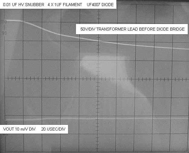
Here are the close-ups of the ringing. That's almost
50V pp on the transformer lead.
The 0.01 uF really reduces the ringing to almost
nothing.
The 0.11 uF reduces the ringing even further, but
the 2 msec/ div waveform showed a jagged response that made me stay with
the 0.01 uF. To make the decision easier, the 0.1 uF was much harder to
fit in the circuit, the 0.01 uF was fairly easy to fit.
This is what I settled for on the final version. The
filament snubbers brought back a little bump the output noise. However,
the reduction in trace noise on the output still does not show up on the
scope photos. The trace with the filament snubbers is much thinner.
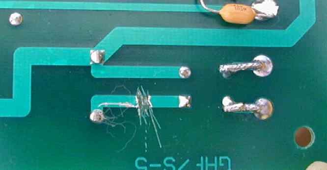
Here is what the 0.01 uF mod look like:
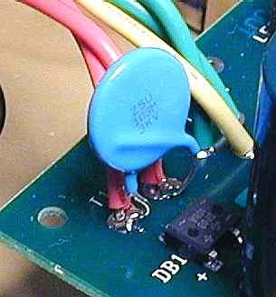
Notice that I made the solder joint as far from the
mounting screw as possible. I pulled the lead insulation up with a
needle nose before making the solder joint. After cleaning, I ohmed the
leads of the cap to the leads of DB1 to verify continuity. Caution: Too
much soldering heat here can ruin your output transformer, transformer
leads and ceramic cap. Hint: Put a paper weight on the transformer leads
to keep them out of the way while I was soldering.

The filament snubber capacitors are 1 uF Z5U 50V
axial caps from Mouser (the bag they are in said 80-C430C105M5U). They
are mounted flush to the printed wiring board (PWB) and the soldering
time was kept short. On the right picture you can see a cotton thread
from the Q-Tip I used to clean the flux off after soldering. 1 uF caps
on all 4 tube filaments may be a bit better, but I'm starting to get low
on my supply of 1 uF ceramics. Next time I order these caps, I'm buying
a larger lot. These solder joints look better in real life than what the
photos show.
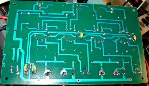
Here is the big picture.
Listening to the amp afterward showed that the
tweeter noise was 100% gone and there was still some low midrange/bass
buzz/hum noise coming out. The sound was much more pleasant with the
snubbers installed. The sound stage had a bit more depth than before.
Occasionally there I could hear some brightness that I'd like to track
down and fix.
The HV snubber also seems to have reduced, but not
eliminated, the pop you get when the power is turned off.
Update: Originally, only two of the tubes have
snubbers across them. When I had my amp open for more B+ capacitor mods,
I added 1 uFs across the remaining two tubes.
HV Snubber Version 2
C-RC
Last update 20-Feb-05
I found a slightly better snubber to use:
First we keep the 0.01 uF across the HV secondary. This cap
needs to be a 2 to 3 kV ceramic or a 400 to 600V film. The ceramic needs
to be higher voltage to keep it from cooking. The films don't get near as
hot.
Next, on the tube side of the 0.01 uF, we add a 0.1 uF (400V or 630V
film). From the other side of the 0.01 uF, we add a 620 ohm 1/4 resistor
to the free leg of the 0.1 uF.
Last, after ohming for shorts, put a pea sized spot of silicon based
glue to hold the capacitors in place. I glued my 0.1 uF to C8, the B+
aluminum.
Tube Filament Inrush Balancing
Last update 12-Feb-05
I have heard that some people can see the tube
filaments come up from left to right on a cold amp (power cord is on the
left.) I was also told that the filament in the tube closest to the
power transformer fails most often at power up. This happens because the
resistance of the circuit card traces limit the inrush to the last
tubes, but the first tube doesn't get this benefit.
We can reduce this issue.
Run a #22 wire from the first tube's pin 4
(filament) to the last tube's pin 4. Then run a separate #22 wire from
the first tube's pin 5 (filament) to the last tube's pin 5 to beef up
the filament traces. Lightly twist these wires (about 2 turns between
each tube). Use one color wire for 4 and a different color wire for 5. IF
YOU DO THIS WRONG AND GET 4 HOOKED TO 5, YOU'LL COOK YOUR POWER
TRANSFORMER AND/ OR THE PWB! Triple check your wiring for shorts
and that pin 4 goes only to pin 4 etc.
If you really want to do this right, when running
the wire, cut back the insulation at each tube and make a solder joint
at each filament. For me, that's just too much work.
Adding an Ultra Fast Diode in Series With
the Diode Bridge.
A standard recovery diode can remain a short for
several microseconds after the transformer voltage drops below the B+
capacitor. During this time current flows the wrong way in the diode
until the diode "recovers" its ability to block voltage. When it does
recover, the parasitics of the transformer tend to ring and radiate
noise because of the reverse current flow. By changing the diode to an
ultrafast diode, we can sometimes cut the unwanted noise energy a factor
of 100 or more.
The K-12M uses a full wave bridge to change the AC
from the transformer into the B+ voltage. If we put just one ultrafast
diode between the standard full wave bridge and the B+ capacitor, we get
the full benefits of ultrafast rectification. We only have to buy one
ultrafast diode to do this. It wouldn't be too hard to replace the
entire bridge with ultrafast diodes, but I want to prove a point here
and show again only one diode is needed.
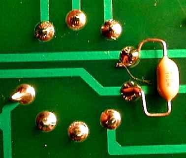
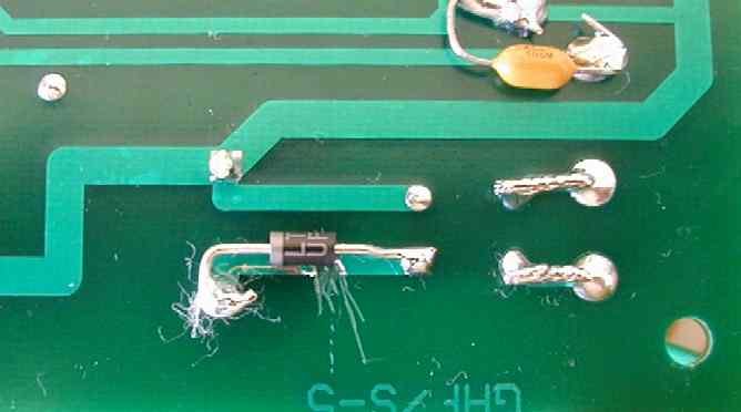
First you have to make an 1/8 cut in the B+ trace
between the first cap and the diode bridge. I like to make a few cuts
with the Xacto Knife and then put some solder on the area to be lifted
out. The heat from the solder makes the trace come up easier. Before
installing the diode, clean any flux and metal off the cut. Before you
go much further, chase down all the metal flakes you just made cutting
the trace and keep them out of the transformer and other circuitry.
This isn't a first class job, but it works. It ohmed
open and I didn't cut my fingers or any other parts! When you wet the
cut with acetone/ alcohol, you can see that there is no metal between
the two traces. The white specs you see in the cut are scratches in the
fiberglass, not metal particles.
Next lay a UF1007 (or UF4007) across the cut as
shown and clean all the new flux off. The diode must be flush against
the PWB.
First the BEFORE Picture. Notice the jagged waveform
on the 50V transformer lead. The jagged slopes on the transformer
windings easily couple energy into adjacent circuits.
With the ultra fast diode installed, notice how
smooth the HV winding is. Smooth edges generally couple less noise.
Here is the close-up of the diode recovery. The bump
on the output is much lower because the ultra fast diode does not dump
as much energy into the transformer as the standard diode does.
The listening test was a positive experience. The
tweeter was still dead silent. The midrange noise was even lower than
before.
By request:
I was requested how to do this mod without cutting the
traces. To do that, you have to replace the diode bridge with four
individual UF4007's. They are wired like this:

Note: I still think having one ultrafast diode in
series with the bridge is just as good as putting in four new ultrafast
diodes. The question boils down to would you rather unsolder the diode
bridge and add 4 diodes or cut one trace and add one diode. If you
decide to unsolder the bridge, I recommend using a very sharp cutter to
cut the leads of the bridge off by the body of the bridge before you
unsolder the leads from the PWB.
Yes, You Still Need Snubbers with UltraFast
Diodes.
Last update 12-Jul-05
Reverse recovery spikes are only one source of noise
and ringing on transformer windings.
Other sources include:
1. Dumping of the energy stored in leakage
inductance at end of charging of the B+ caps in cap input supplies.
2. Dumping of the energy stored in leakage
inductance at zero voltage crossing of the diode bridge in choke input
filters with chokes equal to or bigger than the critical inductance.
3. Dumping of the energy stored in parasitic
capacitance at the zero current crossing of the diode bridge in choke
input filters with chokes less than the critical inductance.
4. Non-sinusoidal current flow in one transformer
winding causing voltage distortion in other winding.
5. Line noise ringing the LC tank made from the
leakage inductance and the capacitance (parasitic capacitance and
purposely added capacitance) on the transformer windings.
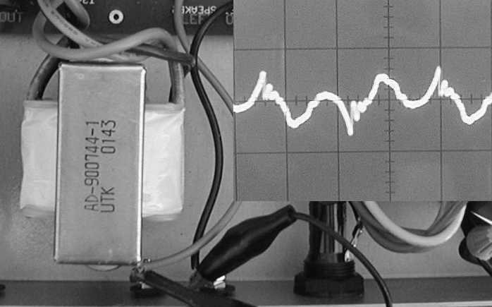
Finding The Best Transformer Rotation
Last update 12-Feb-05
I pulled all four tubes from the amp and placed a
4.7K dummy load on the B+ so the power transformer was conducting
current. I then rotated the transformer to find the lowest coupling with
no load on the output transformer. These pictures were taken with the
0.01 uF HV snubber installed.
This is what the stock left transformer rotation
looked like. (5 mV/div 5 msec/div)
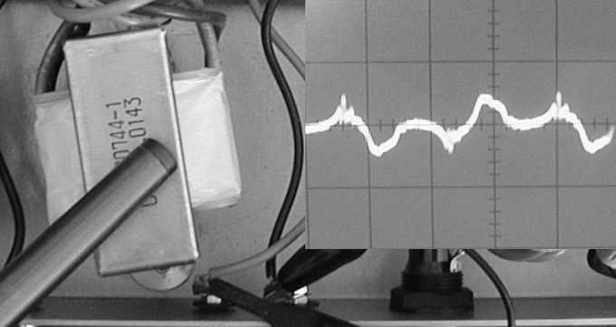
I rotated the top screw hole so that the edge of the
mounting flange was just touching the edge of the existing mounting
hole. This resulted in the best mounting position.
I then continued to rotate the transformer until it
was about 90 degrees from the original mounting. This is about the worst
mounting location. However, this is the easiest mounting location if we
want to install bigger speaker terminals posts.
I repeated these tests on the right transformer, and
it was best at the exact same angle. The flange that on the volume
control side is angled away from the power transformer until it just
touches the edge of the existing hole.
When I remounted the output transformers, I put 1/2L
Flat 25/32" OD Faucet Washers (Neoprene?) under each flange to offer
some vibration damping. This suggestion came with a friend who is into
vibration control in audio equipment. One of the tricks using damping
washers is to tighten the screw so it is just firm, not tight. Then rely
on internal tooth lock washers under the screw and nut to keep the screw
and nut from loosening.
With the Neoprene washers installed, the
transformers and chassis sounded better damped when tapped than with out
the washers under them. Unfortunately, I'm not sure if I heard a big
change in the sound. However, this mod is cheap to do and probably does
help when listened to in a better listening room than my office.
B+ Beef
Last update 12-Feb-05
I was looking at the K12M's B+ and thought it needed
a bit more beef both on the screen supply and the supply that feeds the
driver tubes.
The screen supply (C9, 100u) is much more
sensitive to noise than the B+ itself (C8, 220u) so it needs to be stiff
(low impedance).
The supply that feeds the driver tubes (C5, 22u) also
needs to be low impedance. This will reduce crosstalk between channels
and reduce the sound of the electrolytic in the circuit.
I've got 5 caps and two amps. Since I'm replacing two
of the B+ caps, I'm also planning to replace the third cap, the plate
supply B+ on my second amp.
The cap that looks like the best compromise of being
able to fit and work right is the Nichicon UVR2E331MRD 330 uF 250V cap
Digikey part number 493-1199-ND. These caps have a measured 10 kHz ESR of
0.137 ohms.
Note: A friend of mine has installed these caps in
his amps in all 3 positions and reported that he liked the results.
I've got my caps now. I just put them in the C5 and
C9 position. I had to bend the both leads to get them to fit in the
existing holes. I used a thick bead of Silicon Adhesive on the bottom of
the caps to the PWB to keep the caps from wiggling too much. This
mod is worth it. There is a noticeable increase in focus and solidity to
the sound stage as the volume changes that wasn't there before.
When bending the leads, they get bent into
a Z. Hold a needle nose pliers on the lead flush against the cap's body
to make the first bend. Place the cap so that it almost hangs over the
edge of the PWB.
Halo Tube Dampers
Last update 6-Feb-05
Hal-O
Tube Dampers These helped. I tried these so long ago,
I can't remember the exact differences other than I like it. They've
helped on 12AU7s, 12AT7s these 11MS8 tubes. I didn't hear much on my
good 2A3s. I haven't tried them on my microphonic 2A3s.
CCS FOR DIFFERENTIAL OUTPUT TUBES
Last update 19-Feb-05
The 300 ohm 3W cathode resistors R8 and R17 are replaced with a simple
constant current source. Because the tubes were running so hot, I dropped
the current a bit below the stock bias point. The stock bias was 86 mA
(~8.2W per plate). I set the CCS current to 75 mA (~6.5W per plate). This
CCS has an LED in it just for show, it can be removed to simplify the
circuit. If the LED is removed, keep R5 and R6 in the circuit to help the
FET to run cooler. It takes about 5 to 10 seconds of power being applied
before the LED lights up.
I used parts from several old Digikey orders to build this. Here's the
parts list for one channel:
Radio Shack
1 1.0" by 1.5" perf board
1 Radio Shack RED
LED (D4)
ACE Hardware
1 #4 1 inch screw, flat, split and nut.
1 1/2 inch nylon standoff (This is glued under the
perfboard to the PWB to hole the mod in place.)
1 Silicon Adhesive.
Digikey
1
HS301-ND (Heatsink)
1
BER113-ND
(K10
thermal Pad)
3 1N5234DO35MSCT-ND (D1, D2, D3)
1
IRFIBF20G-ND (Q1)
2 P20.0CACT-ND (R5,
R6)
1 BC130W-1CT-ND (R1) <-- 1 Watt (Or use
110 ohm 1W and not install R8)
2 P110CACT-ND (R4,
R7 or 100 ohm)
2 P140KCACT-ND (R2, R3)
I used a different part for this in the picture below,
any
140K 1/4 is good enough.
1
493-1554-ND (C1)
Fry's Electronics
1 R8 / Rtrim (I used an NTE 620 ohm 1/4W
film ), leave R8 out Or use a Digikey P620CACT-ND
Here's the part's placement and wiring guide part side view.
Here's a close up of the finished CCS. The 130 ohm 1W resistor is stood
1/4 inch above the perf board to keep it from browning the board over
time. The heatsink was mounted by drilling the holes in the perf board
open to the holes a bit and pushing the perf board onto the heatsink pins
with a large flat bladed screwdriver. The holes for the FET lead were
enlarge a bit too.

Here's the amp with the Hal-O's, rotated output transformers, B+_Beef,
C-RC snubber and CCS'd cathodes on the output tubes.

The CCS on the output tubes improved the smoothness of the sound.
CCS FOR DIFFERENTIAL OUTPUT TUBES
Last update 15-Aug-05
One set of tubes in my amp weren't matched very well so I manually
balanced the bias by trimming a set of grid bias resistors. I have a
better way of doing the balance and it is shown below. I haven't made my
version of this circuit, but I've shared it with a few people who wanted
to try it. Notice that R2 and R3 have dropped in value to support the bias
current for R10 and R11.

Setting the bias point Version 1
To set the bias point, with the power off, the capacitors discharged and
the unit unplugged, measure the ohms from the plate of each tube to the
center tap of the output transformer. Write these numbers down. With the
power off, clip the red lead of the DVM to the CT of the output
transformer. Let the tubes warm up and then with the black lead, carefully
measure the voltage from the center tap to the plate of each tube at the
same point you measured the resistance. Turn the power off and wait for
the caps to bleed down before moving the leads to the next output
transformer.
From this calculate the the bias current.
I_BIAS = V_LEFT / R_LEFT + V_RIGHT / R_RIGHT
Then calculate the voltage you need read in order to trim the pot.
V_LEFT_Balanced = R_LEFT * I_BIAS/2
Setting the bias point Version 2
To set the bias point, with the power off, the capacitors discharged and
the unit unplugged, measure the ohms from the plate of each tube to the
center tap of the output transformer. Now in series with the winding that
had the lowest ohms, add a 1W (2W or 5W) resistor. Double check your ohm
measurements after it is installed. You want to get the resistances
measured from the plate to the CT to be less than 5% (2% goal.)
Now clip the DVM between the plates of the two tubes, turn the power on,
let the tubes warm up and adjust the balance pot for zero volts dc between
the plates of the two tubes. Turn the power off and wait for the caps to
bleed down before moving the leads to the next output transformer.
Ideas for future mods:
1. Add a safety bleeder on B+ (390K
1/2W) (Done with bias resistor in CCS.)
2. Replace C1 and C4 with a 100K metal film and
convert the volume control to shunt mode. This could go in series with
C1 and C4 if you want to keep the DC blocking.
3. Upgrade the coupling caps to polypropylene.
4. Possibly add a grid stop on the output tubes (On
the trail for a brightness fix.)
5. Possible add an RC zobel across the primary (On
the trail for a brightness fix.) Tried it, it wasn't worth it.
6. Add a single ultrafast diode between the diode
bridge and the first cap. You don't have to replace the entire
bridge! One diode here is good enough. (Lower output noise.) - DONE
Worked great
7. Use a CCS for R10 and R2 in the first gain stage.
(It did wonders all the other times I C4S's something.)
8. CCS the output differential pair. - DONE
Worked great
9. See how far I can drop the output impedance and
still have a stable amp. (I got to play.)
10. Add another B+ filtering stage for the output
tube or increase the B+ capacitor values. (Lower output noise,
tighter bass.) - Done Bigger caps are RECOMMENDED
11. PDMPS the driver stages. (Chasing a wider sound
stage.)
12. Neoprene bushings under between the power
transformer and case (The line transformer's case should go to safety
ground.) - Done. I used DANCO 1/2L Flat Faucet Washers 25/32" O.D.
Stem Repair P/N 88578 (Ace Hardware?) Looked cool, but didn't
help the sound a lot.
13. Raise the filament voltages about 50V above
ground to try to reduce hum further.
14. Add balance adjust for output stage bias current.
(Done with discrete resistors, I have plans to put in a bias
balance (bass balance pot) in the near future. One pair of tubes were
not matched very well, the other pair was dead on matched..)
15. Beef up copper in filament traces. (Done. The
tube seem to share the inrush current nicely.)
.
First release 20 Apr 2003 AM, Last update 15-Aug-05
This web page may not be copied nor reprinted in any form..

 _
_
