If you wish to implement multiple outputs with one coupling cap, only one 470K output bleeder is needed. R5 is not actually needed. R4 can be moved to the left side of R2 if so desired. One 470K on each output won't hurt anything but your wallet, but you'd be better off moving R4 to the left of R2 instead of adding R5.
If you want to use more than one coupling capacitor, a 470K will be needed for each coupling cap as shown on AUX_2_OUT.

Interaction between two outputs is possible. That is why it is recommended to add a 4.7K in series with each output. 4.7K is a good compromise between noise pick up and cross talk rejection. You can go lower than 4.7K, but I wouldn't go below 100 ohms. If you don't like the sound of 4.7K, try 1K before you to to 100 ohms.
This is the isolation between outputs you get with
different values for R2, R3 and R6 with the stock output capacitor.

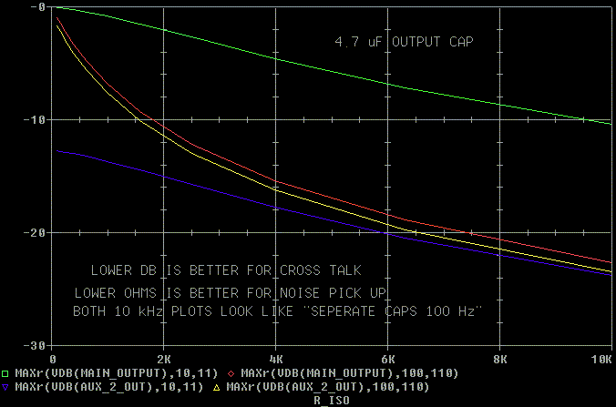
If you increase the output coupling cap to 4.7 uF
(about as big as you want to go) you'll get this type of crosstalk
between outputs.

The order of the traces is the same, but the colors changes on me when I made the plot. You can see that you get a lot of midrange isolation with 4.7K. 1K has a worthwhile amount of isolation. 100 ohms doesn't offer any isolation, but will keep the interconnect cables from ringing as much at high frequencies. (You can CTRL-N to open a new browser window so you can put the graphs side by side.)
Why do we want isolation?
Imagine forward biasing the grid (so that the grid draws current) in the amp attached to AUX_1_OUT. The 4.7K would limit the distortion fed back into the cathode of the Foreplay and reduce the distortion fed into the MAIN_OUTPUT.
With this in mind, individual caps are better than one cap. HOWEVER, the Foreplay is in an unshielded case. With more caps you'll get more surface area to pick up EMI (ElectroMagnetic Interference). This EMI can come from both the Foreplay's power supply and from any other EMI sources around your house or city. Darn, there ain't no such thing as a free lunch.
If one of the amps is solid state, replace the words "forward biasing the grid" with the words "slew rate limit", "clip", "have a non-linear input impedance", "have the power turned off", etc.
There are other effects that can happen too. Forward biasing a grid is a gross problem. There are other crosstalk problems than can occur that are more subtle than non-linear inputs including the crossfeeding of distortion. Another one of them is: nothing happens at all. Start with the simplest approach and add to it later if you get bored or if you actually don't like what you are hearing.
.
 ( New
2024 index page.)
 _( Old 2003 index page.)
 _( AMP Second index
page.)
 ( Fancy index page.)