
MODELED and TESTED
It was about 1/2 as hard as the preamp itself
was to build.
I used C1 = 470 uF 35V (Radio Shack) and C2 =
180 uF 63V (Digikey).
With a 100V DC supply, the turn on delay was
8.5 seconds and the current stopped rising after 22 seconds.
I was curious what an active load for the Chaperone output would sound like. I wanted the active load to have a turn-on delay that automatically reset when the high voltage power supply dropped below a certain level. If it did not have an automatic reset circuit, it could take an hour to completely discharge on its own. This is the circuit I am going to try:
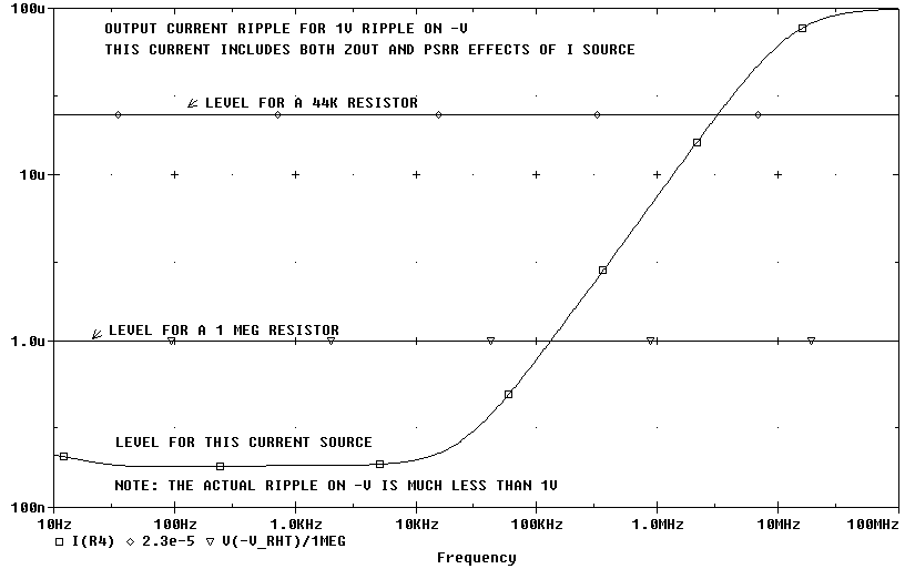
This figure above shows the power supply rejection Pspice thinks the
Chaperone Current Source will have.
Note: My 6.2V zeners are running at 5.8V because of the low current they
are biased with.

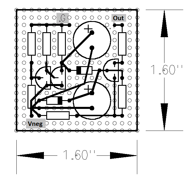
This is the X-ray view of the wiring diagram from the top. The wires are all on the back side of the perf board. The wires are not shown as dashed lines (hidden lines) because the dashes were hard to see on a web page. "G" goes to ground. "Out" goes to the cathode of the tube. "Vneg" goes to the -100V.
I had only hoped for an reasonable improvement of the turn-on thump. What I got was a huge improvement in the turn-on thump and a very noticeable improvement in the sound. The sound was much silkier now and lost none of it's detail and image. .
 ( New
2024 index page.)
( New
2024 index page.)
 _( Old 2003 index page.)
 _( AMP Second index
page.)
_( AMP Second index
page.)
 ( Fancy index page.)