Do I cover everything? No. I don't know everything and if I did, I'd
probably loose sight of the goal: A good sounding amplifier.
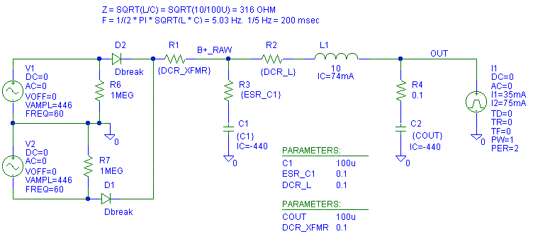
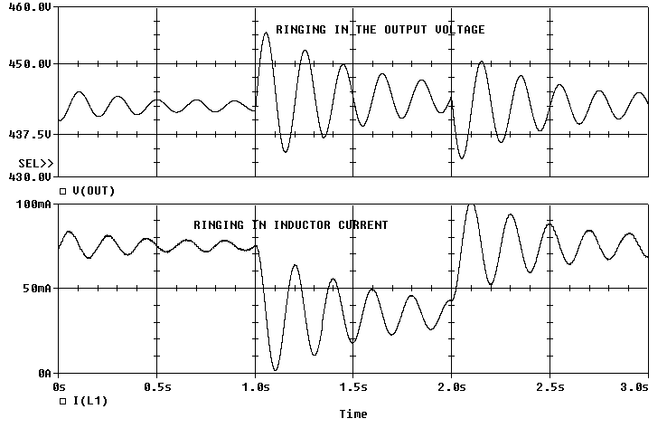
The first case I want to present is with a current source load going from 35 mA to 75 mA on the output.
One instance this example would represent is a CLC supply feeding a series voltage regulator. This first case is not too real because of the "unrealistic part values", but I want to show it to get your attention.

The only source of damping in this circuit is from the voltage change on C1 between 60 Hz charging pulses from D1 and D2.
Why would you care if this is feeding a voltage regulator?
You would care if the voltage ringing got big enough that it caused the voltage regulator to run out of voltage head room (the regulator saturates) or the ringing got high enough to damage the regulator. I've actually modeled and seen a worse performing circuit, but that was years ago and I doubt I could get permission to publish the schematic.
Now lets look at other things that affect the ringing.
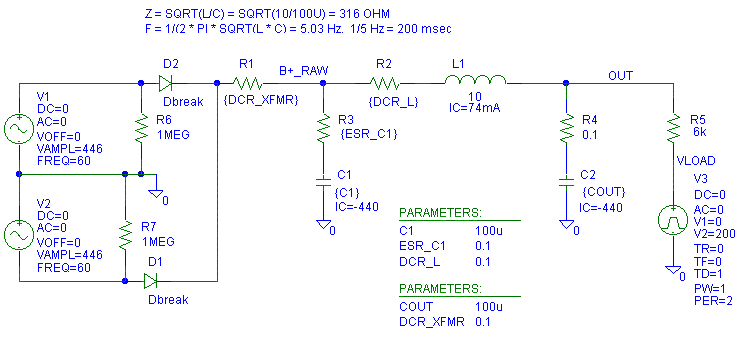
First a new schematic. All that was changed was that the current source load is now a 6K resistor (5K transformer + 1K plate) being fed by a 200V voltage step in voltage. This step in voltage represents a load change from a tube.
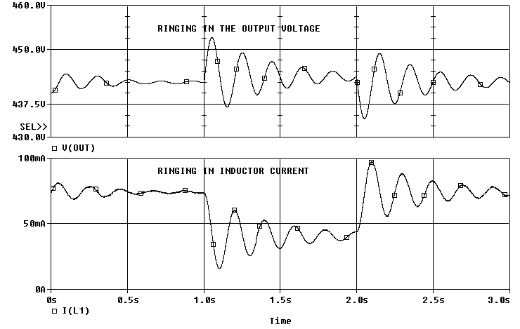
Notice that the ringing dies out much quicker.
Why?It is because the 6 K load is dissipating the ringing energy in to the 6 K load.
What did we learn here? The load can damp the CLC filter. This may or may not be a good thing. IMHO, the power supply needs to be stable for the load, not because of it.
How else can we get rid of the ringing? I said before that C1 could add damping to the CLC tank. This is because as more current is drawn from C1, the change is voltage across C1 increases between line cycles. This change in peak to peak voltage lowers the average DC output voltage. Effectively, C1 looks like a resistor in series with DC supply. A rough estimate of this "effective" resistor value is found by these equations:
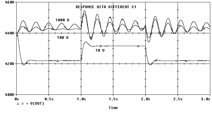
I = C dV/ dt (the capacitor formula)Lets set C1 = 10u, 100u and 1000u and see what happens. Notice that at 10u the output voltage drops a lot in DC voltage, but has almost no ringing. The 1000u rings like a bell. For both 100 u and 1000 u the DC regulation (the voltage change after the ringing dies out) is good. What did we learn here? The first capacitor after the rectifiers affects both damping and regulation. Bigger is not necessary better in this location. As we will find out later, a large capacitor for C2 (C_out) is where to put your money.
R = V/I (the resistor formula)Set I = 1 amp, dt = 8 msec (approximate time between crests with full wave rectification at 60 Hz) and solve for average voltage drop on capacitor. The average will be about 1/2 the dV (change in voltage.)dV = 1 A * 8 msec/ C for 1AIf the voltage changes 1V average for a 1A change in current the resistance is 1 ohm. If we use 1 A in the calculations: the answer comes out in ohms, the answer will be valid for other currents and using 1 A makes the equations look nicer.
The average is = dV/ 2
So the average dV/ 2 = [ 1 A * 8 msec/ C /2 ]Divide the average voltage change for 1 A load change by 1A to get the resistance.
R_eq = [ 1 A * 8 msec/ C /2 ]/ 1 A = (8 msec/ C)/ 2 = 4 msec/ C
R_eq_C1 = 4 msec/ C1
R_eq_C1 = 4 msec/ 100 u = 40 ohms.
From the Pspice data: [ 1.4 V change in V( out ) ]/ { 33 mA change in I( L1 ) } = 42 ohms
Note: A big capacitor in for C1 also increases the RMS current in the transformer for the same amount of load current. Link to Doom and Gloom predicted for too large of a capacitor after a diode bridge.
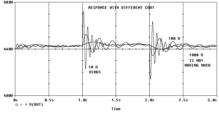
Now lets set C1 back to 100 u and change C2 (C_out) to 10 u, 100 u and 1000 u. At C_out = 10 u the output rings fast and with a large amplitude. With C_out = 1000 u, the output rings slowly and at a lower amplitude. What did we learn here? A bigger output capacitor usually helps with the ringing and is good. However if the ringing still exists, it will be pushed to a lower frequency which may or may not be desirable.
I have heard of people using the ringing in the power supply to "warm up" the sound of an amplifier. Now we get into a taste issue. I personally will give up bass volume for better bass definition (each note is heard as a different note versus having the windows rattle.) I know a lot of people who will give the bass tightness up to get more bass quantity.
Why is C_out = 1000 u not ringing as much as with C_out = 100 u?
At C_out = 1000 u, Zo of the filter = sqrt( 10 H/ 1000 u) = 100 ohms. C1 at 100 u has a effective equivalent resistance of 40 ohms. So the Q_series would be 100/ 40 = 2.5.At C_out = 100 u, Zo of the filter is 316 ohms. So Q_series would be 316/ 40 = 7.9. The lower the Q, the fewer rings it takes for the ringing to die out. (More on Q in an upcoming web page.)
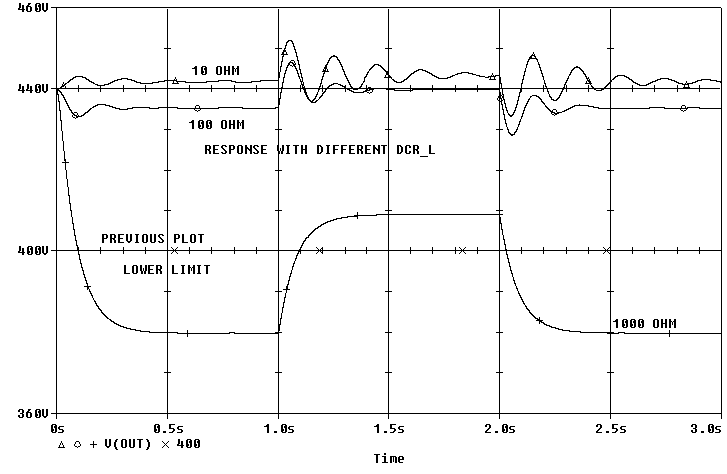
Now let's put C1 and C2 (C_out) back to 100 u and set DCR_L to 10, 100 and 1000 ohms. As expected with large resistances, the damping is good, but the regulation is poor. Care must be taken to not over do series losses. They hurt the DC/low frequency regulation of the supply. With really low values of DCR, the ringing gets worse. What did we learn here? Low DCR in the inductor is good, but it can be over done. If you buy a low DCR inductor, lower the Zo of the LC tank by buying a larger capacitor for C_out. (More on L, C and Q in an upcoming web page.) That way the DCR of the inductor can help de-Q the LC tank.
Also keep in mind, with a different value L and/or C_out, the effect of 100 ohms DCR in the inductor will be different. This is because the Zo of the LC tank will be different. Zo = sqrt( L/ C ).
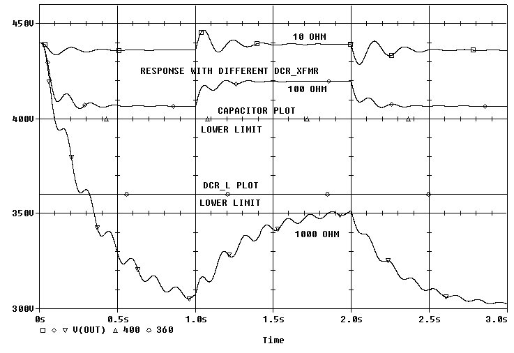
Now lets change the DCR_XFMR between 10, 100 and 1000 ohms with the DCR_L back to 0.1 ohms. Notice, 10 ohms of resistance in the transformer hurts the regulation more than 10 ohms of resistance in the inductor. When the resistance gets to 1000 ohms, the transformer is no longer controlling the voltage across C1. With 1000 ohms DCR_L, C1 now behaves like a capacitor in the circuit, not just as an effective resistor. What did we learn here? Low DCR in the transformer is good. Unfortunately, almost nobody specifies regulation or resistance in their catalog.
Now play with the ESR of C1. The DCR of the transformer is set back to 0.1 ohm. There is not much change from 1 ohm to 10 ohm ESR in the capacitor (these are normal values of ESR for a 100 u 500 V aluminum electrolytic capacitor.) The regulation is better with the 1 ohm than with the 10 or 100 ohm ESR values. Even at 100 ohm the ESR does not cure the ringing, the regulation is suffering. What did we learn here? Low ESR in C1 is good.
ESR also affects the high frequency noise and high frequency performance of the power supply. Low ESR keeps the impedance of the power supply low at high frequencies.
Note: Not only can you buy different models of capacitors with different
ESRs, but as the capacitor ages and dries out, the ESR will go up. An
increase in ESR is the first indication the capacitor is about to die.

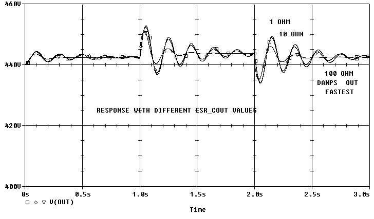
Now lets just vary the ESR of C_out. At first glance, it looks like a high ESR in C_OUT is good! However, there is more to the story. (There is more to the story on every picture above, but this is the one picture it is easiest to get into trouble with.) 1 and 10 ohms ESR do not really change to low frequency ringing. 100 ohms does damp the ringing. HOWEVER, the ESR sets the high frequency performance of the supply. We need the power supply to be a quiet, clean and have zero output impedance at all frequencies, but this is especially true at high frequencies where we are more sensitive to noise.
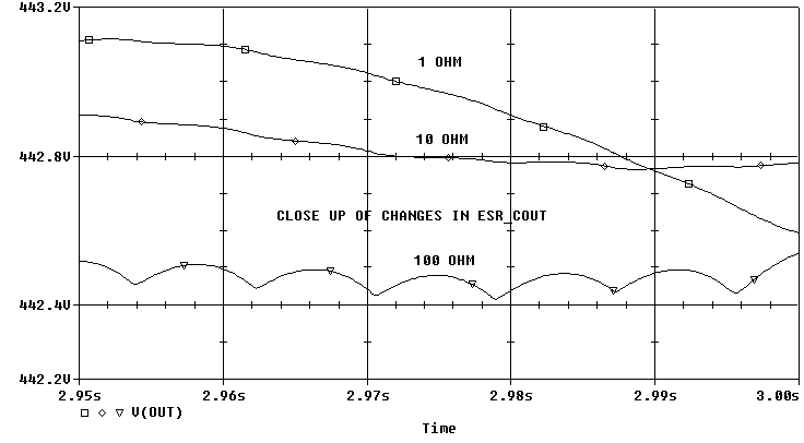
Lets look up close at the voltages from the picture above. Notice in the plot below how at 100 ohms the output ripple is so much larger than at 10 or at 1 ohms. What did we learn here? Low ESR in C_out is good. High ESR in C_out may help damp the LC tank, but it gives up other important parameters like output ripple and output impedance at high frequencies.
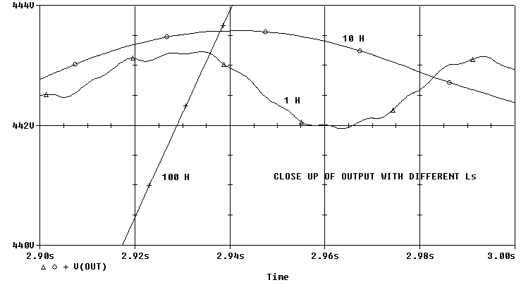
Now lets just change L between 1, 10 and 100 H. Remember, the only losses in the circuit are the 6 K load resistance and the effective resistance of C1 (40 ohms). We see that with 100 H we get some drastic voltage ringing with the step load. We'll need to look at a close up picture to see the problem with the 1 H choke.

The 100 H choke has very little high frequency ripple. The 1 H choke has visible ripple. The 10 H (with this combination of parts!) looks like it may have reasonable ripple (if the ringing is ignored.) What did we learn here? Too much or too little L in a CLC power supply may hurt performance.

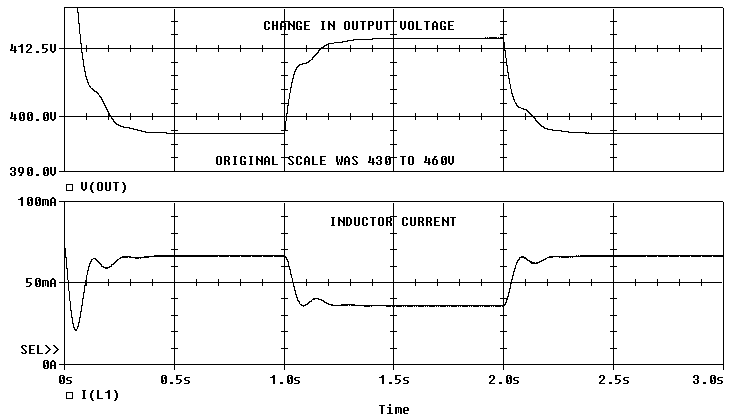
The step load looks good, just lacking in some "DC" regulation:
Many times CLC filters just fall into place and work great. I hope the info in this web page helps you out if you run into any problems.
* The load can damp the CLC filter. This may or may not be a good thing.
* The first capacitor after the rectifiers affects both damping and
regulation. Bigger is not necessary better in this location
* A bigger output capacitor usually helps with the ringing and is good.
However if the ringing still exists, it will be pushed to a lower
frequency which may or may not be desirable.
* Low DCR in the inductor is good, but it can be over done.
* Low DCR in the transformer is good. Unfortunately, almost nobody
specifies regulation or resistance in their catalog. Don't bother them
about it either unless you are intending to buy hundreds of their parts.
* Low ESR in C1 is good.
* Low ESR in C_out is good.
* Too much or too little L in a CLC power supply may hurt performance.
* The best part value varies from application to application.
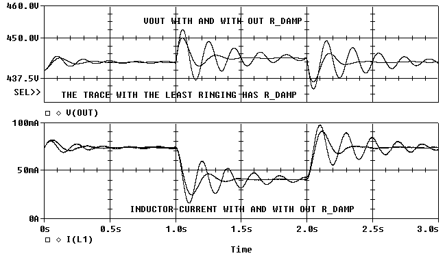
First let's add 420 ohm and 100 uF in series across the existing 100 uF in the "unrealistic parts" schematic:

Notice how with the addition of R8 (R_damp) and C3 the ringing dies out much faster.
Also notice that C3 has a large value resistor in series with it. This means C3 can be less expensive than C2. The resistor will hide most of the sonic faults of C3 (if any) because C2's impedance should dominate the parallel combination of C2 and C3/ R8.
For example, if C2 were a film and foil capacitor, C3 could be an aluminum electrolytic capacitor. If C3 is twice C2, even more damping can be achieved. The best value of R8 is a function of the ratio of C3/ C2 and the sqrt( L1/ C2 ). Note: I have not tried this in a tube power amp, but I have tried it in other circuits and it worked well.
This is also the same concept as the "Lossy Parafeed" capacitor I put in my Paramour.
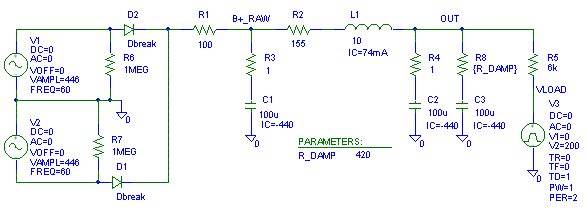
Next let's add 420 ohm and 100 uF in series across the existing 100 uF in the reasonable part values schematic:
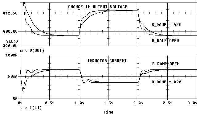
Notice that the excess ringing in the output voltage is reduced. The slower rise and fall time is because the output now has more capacitance, but it is a lossy capacitance so that more of the ringing energy goes into R8 (R_DAMP) instead of other components, like the load resistance (R5).
First edition 6-Jan-01, last update 1/17/01
I don't
change the update date on individual sections for minor corrections.
I only change the date for content changes..
 ( New
2024 index page.)
 _( Old 2003 index page.)
 _( AMP Second index
page.)
 ( Fancy index page.)