This page deals with untried circuits and high
voltages.
High voltages can cause fatal and/ or serious damage and harm to your
body.
Use the information here are your own risk.
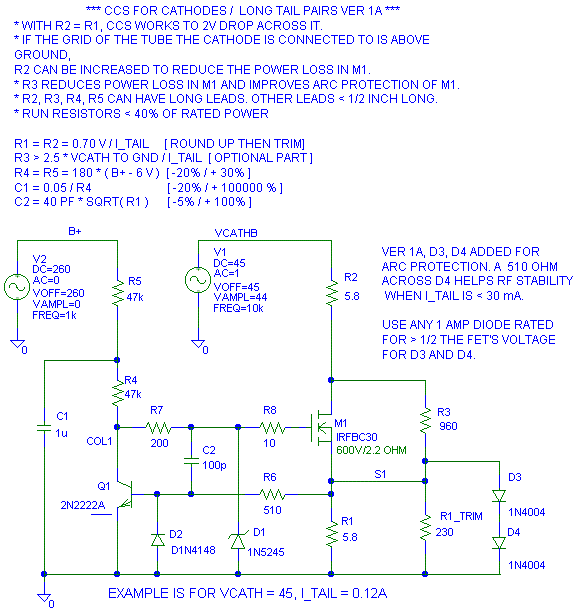
Here is an example of a solid state CCS designed
for biasing up cathodes:

One of the things I hear when I post this is why the heck do we need all these parts? The answer is because that is what it takes to do it right.
Let's strip this down and go through why each part is there. First the low hanging fruit:
1. R1 is the current set resistor. It is good to go a bit high on the value of R1 so you can solder R1_TRIM across it to raise the current to where you want it to be. Soldering a resistor across another resistor is much easier than unsoldering an existing part and changing it out.
2. Q1 actually regulates the output current. When the voltage across R1 gets big enough to turn Q1, Q1 turns M1 off and regulation occurs. A single NPN with high gain is what we want for Q1.
3. M1 is the output stage.
3.1 Look for a part with low Crss and high voltage rating. You want the voltage rating to be high enough so when the tube arcs at high ac line and light B+ load, the voltage rating of the FET is not exceeded.4. R4 (and R5) provides the bias current to drive M1 and Q1. Too little current and the CCS could have slew rate problems if the load decides to move fast. Too much current and parts get hot.3.2 Look for a part that is easy to heatsink. The wattage rating on these parts is with the part attached to a cold plate with the mounting tab held at 25C with enough heat pumped into them to raise the junction to maximum rated temperature. We're lucky to get 10% of that rating when we use the part in a circuit we want to last for a few years.
I'm starting to like the IRFIBC style FETs because they have a fairly rugged plastic overcoat so you don't have to worry about the mounting screw arcing to the drain (metal tab) on the part. The problem with these parts is that they have a high RthJC of around 4 C/W.
3.3 Silicon (FET/ Diodes/ Transistors) does not have a sense of humor when it comes to voltage. Sometimes you get lucky and the 1000V part doesn't die at 1010V, sometimes you don't. Silicon is rated for its instantaneous peak voltage, not the voltage where you can bias it up to. Silicon can have accumulative / latent damage from over voltage stress. You can over stress it on Monday and have it fail on Wednesday.
5. D1 is needed to protect M1 for several reasons.
5.1 If VCATHB doesn't exist or is too low for the CCS to operate, R4 will pull the gate of M1 up to B+ and the FET will die a quick death.6. R8 is the grid stop/ gate stop resistor. This keeps the FET from oscillating at VHF. The FET doesn't care if you only want it to work in the audio range. It will operate to as high a frequency as it can and if the wiring parasitics aren't just right, the FET will oscillate (just like a 6DJ8 etc will.) So use the grid stop resistor.5.2 FETs have a large amount of capacitance from drain to gate. This capacitance is large enough when compared to the capacitance from gate to source that when the drain (attached to VCATHB) rises rapidly (due to an arc) or falls rapidly, the gate can reach voltages that can damage M1's gate or even damage Q1.
7. R6 protects Q1 from M1's drain to source
capacitance. It is easy to pump a lot of current through this
capacitance as we'll see later.
I don't change the update date on individual sections for minor corrections. I only change the date for content changes. . .
 ( New
2024 index page.)
 _( Old 2003 index page.)
 _( AMP Second index
page.)
 ( Fancy index page.)