Note: I have a fancier delay in my Chaperone Preamp.
This involves working with high voltages,
attempt this at your own risk.
Added 12/25/00 Updated 12/25/00
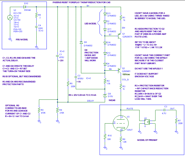
I recommend that you place a resistor between the C4S and the tube that it is driving. This provides a little protection against tube faults and power up/ power down stress. It also isolates the tube from the output capacitance of the C4S at RF frequencies. The bigger the series resistor value is, the better the protection, but the less voltage swing you will have available out of the C4s.Here is the "Napkin" sketch of the changes. Do not freak out at the number of parts. Only 5 parts are really needed. Some of the parts in the schematic were necessary to get free version of Pspice to run the way I wanted it to. The delay caps will be about 3/4 inch diameter and 1 1/4 inch long.I'd make this series resistor bigger than R = B+/ (Ic rated of C4S transistors). For most cases, Ic rated will be around 0.5A and B+ will be less than 300V so R_series min = 300 V/ 0.5 A = 600 ohms. This resistor is R3 in the schematic below. If you install this resistor, make sure the leads of the resistor are anchored and cannot short to anything else.
In addition to this resistor I would add one 1 amp diode (1N4002 works fine) across both C4S LEDs in each C4S.
One side of the added diode needs to attach to the base of the bigger output transistor. The other side of the diode attaches to terminal A.For the delay to work, no changes are needed to the C4S that biases the output tube to ground. I would add the series resistor and protection diode to this C4S too. Keep in mind that the cathode (band), not the anode, of the protection diode will be going to the base of the cascode transistor in output tube's C4S.For polarity: The cathode of the added diode goes to the anode of the LED. The anode of the added diode goes to the cathode of the other LED. This diode is D6 in the schematic below.
You may need a 2 meg resistor from the plate to ground to make this circuit work right. I'd try it with out the resistor first.
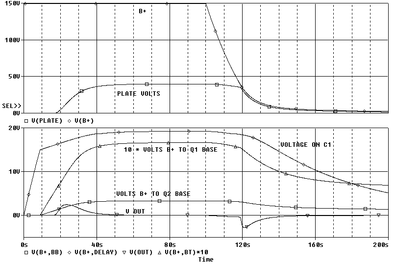
Here is what Pspice says the delay mod will do at power up and power down. Note that you have to wait a long time before the delay will give you protection against the next power on thump. The fix for that is fancier yet and is not shown on this page. The turn-on is delayed about 16 seconds.
The turn-on thump is 2.4V peak. The 200K output resistance is the preamp's internal 470K in parallel with 348K in the power amp's input. I am using 4.7 uF for the output coupling capacitor because that is what I have in my Foreplay. The turn-off thump is -2.8V. If R7 (the output resistor) is reduced further, the output thump becomes even smaller.
 ( New
2024 index page.)
( New
2024 index page.)
 _( Old 2003 index page.)
 _( AMP Second index
page.)
_( AMP Second index
page.)
 ( Fancy index page.)