At the time I ordered it, the only mods I'd heard about were a bigger 9V transformer, pulling the tube and changing the opamp. The power ferrite on the power cord is my own trick.
When the DIO came in, I let it play for 1 full CD before listening to it. It did not sound as good as my Creek at this point. Also, I could only get sound out of it in the 44.1 kHz mode at this point. I'm not sure what I was doing wrong.
So I pulled the tube,With just a 1 uF across the transformer (CR1 anode to CR11 cathode), the ringing frequency of the diode recovery changed more than the amplitude did. From the new ringing frequency from the diode recovery (4.8 kHz) with 1.2 uF of capacitance, I calculated the circuit leakage inductance was 0.9 mH. When I added the RC snubber, the many cycles of ringing dropped to about 1-1/2 to 2 cycles of ringing.
put a 1 uF X7R from CR1 Anode (the transformer hot) to CR11 Cathode (GND)
put a 56 ohms in series with another 1 uF at the power input jack and
put a 22K from each of U1's outputs (pin 1, 7, 8 and 14) to -15V (pin 11).
So I listened again. At this point the back ground was quieter, but the music was flat both in the sound stage and dynamics.
I went surfing for mods. Here are a couple neat sites.
Site on Anglefire about ART DI/O.
Summary of ART DI/O mods in Digital Asylum
Craig Fraser's Site
Bolder Cable will do the mods for you (Link Broken).
I bought my ART DIO here. They asked if I wanted to drop ship it to Bolder Cables! (Link Broken)!
I then pulled the schematic off of Yahoo
Art DI/O group (you must join to read files.) (Link Broken)
Art Dio Digital Schematic (PDF)
Art Dio Analog Schematic (PDF)
This time I went in and:
Put yellow tacky wax on the crystals,This was even quieter, gave me some sound stage, cleaner (but less bass) and the ability to operate in external sync (which sounded better.) Note: The tacky wax must not touch any other part for it to damp vibration on the crystals. I had to removed the digital card once to adjust the amount of wax.
removed R2, R2, C8 (cap multiplier),
removed and shorted out C17, C18 (output caps),
removed C15, C14 (input caps) and
made C59, C60 0.01 uF NPO
I also tried a clamp-on ferrite bead (about 1 inch long) on the digital input cable. This did more good than the choke on the 9V power cord.
34.8K 1% R13, R15, R14, R18, R19, R20, R22, R24
2.10K 1% R16, R17, R21, R23
330 1% R7, R9I like having a resistor between the opamp and RCA (R7 and R9). It isolates the cable capacitance from the op amp. It also gives better short circuit protection and a tiny bit of ESD protection.
R10 1% 76 ohm S/PDIF termination.This made comparisons between the DIO and the Creek easier (they were about the same volume.) The DIO sounded a tiny bit better, almost the equal of the Creek.removed R6, R8 (10K output cap bleeders)
changed C24, C34 to be 100 pF NPO,
shorted J1 pins 1, 2, 3 on the main card (analog inputs to ground)Note: I had to trim the tacky wax again. Upon power up, I noticed that the offset voltage of one of the channels was 1400 mV and the other channel was 16 mV. I had swapped one of the 34.8K and 2.1K resistors. With multiple ohm readings, I found out which ones were swapped.
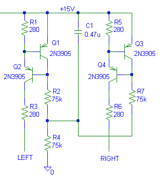
Now I got serious. I looked at the internal block diagram for the TL074 and saw that if I biased it to the positive rail with a CCS the music only went through one diode junction on the output stage instead of four. This also biases the output class A. Some op-amps like to be biased to the positive rail, some to the negative rail. Usually the rail with the least diode junctions through the signal path works the best.
I didn't have any JFETs on hand to build the CCS from the DIO links. I'm not found of JFET CCS's. The last time I used a JFET, I had trouble with repeat-ability. So I put together a standard CCS using PNP transistors. I used 280 ohm resistors instead of 270 ohm resistors because I had them.

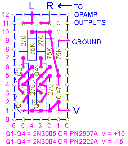
Here is a fairly tight perfboard layout I used
in my DIO. The 0.47 uF is a X7R ceramic.

Use these changes at your own risk. I'm not
supporting them. Several friends of mine keep asking me to resend my
notes so I put up a page on it.
Also see Another list of Art Dio Mods
.
First edition 08/16/02, last update 08/16/02
I don't change the update date on individual sections for minor
corrections.
I only change the date for content changes.
2-Jan-05 included the perfboard layout for the current
source.
 ( New 2024 index page.)
 _( Old 2003
index page.)
 _(
AMP Second index page.)
 ( Fancy index page.)